Rare earth magnet having high strength and high electrical resistance

a magnet and high-voltage technology, applied in the direction of magnetic materials, magnetic bodies, transportation and packaging, etc., can solve the problems of insufficient mechanical strength of high-voltage magnets, large eddy current loss, and decrease the efficiency of motors, so as to achieve high-voltage resistance, high-voltage resistance, and severe vibration

Inactive Publication Date: 2006-12-28
NISSAN MOTOR CO LTD
View PDF5 Cites 32 Cited by
  • Summary
  • Abstract
  • Description
  • Claims
  • Application Information

AI Technical Summary

Benefits of technology

[0051] The rare earth magnet having high strength and high electrical resistance of the present invention is capable of enduring severe vibration because of the high str...

Problems solved by technology

However, the ordinary R—Fe—B-based rare earth magnet is a metallic magnet and therefore has low electrical resistance which, when used in a motor, causes a large eddy current loss that decreases the efficiency of the motor through heat generation from the magnet and other factors.
However, since the rare earth magnet of the prior art that has high elect...

Method used


Image

  • Rare earth magnet having high strength and high electrical resistance
  • Rare earth magnet having high strength and high electrical resistance
  • Rare earth magnet having high strength and high electrical resistance

Examples


example 2

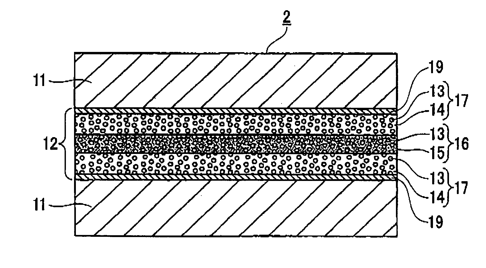
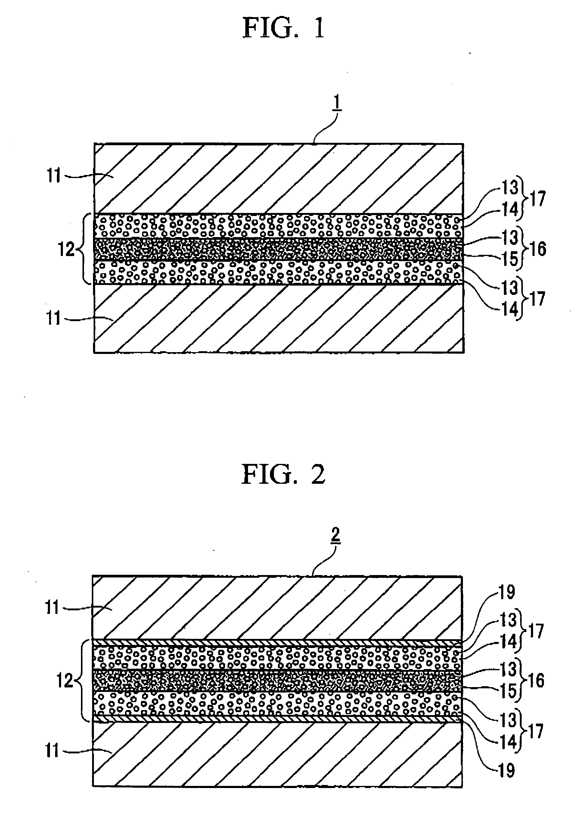
[0135] R oxide powders made of Dy2O3, Pr2O3, La2O3, Nd2O3, CeO2, Tb2O3, Gd2O3, Pr2O3, Y2O3, Er2O3, and Sm2O3 were adhered using 0.1% by weight of PVA to the surface of the R—Fe—B-based rare earth magnet powders A through T previously prepared by HDDR treatment shown in Table 1, to a thickness of 2 μm, and glass powders shown in Tables 6 through 9 were further adhered thereon with 0.1% by weight of PVA (polyvinyl alcohol), thereby to prepare the oxide-coated R—Fe—B-based rare earth magnet powder. The oxide-coated R—Fe—B-based rare earth magnet powder was subjected to heat treatment at a temperature of 450° C. in vacuum so as to remove the PVA, followed by preliminary forming in a magnetic field under a pressure of 49 MPa and hot pressing at a temperature of 730° C. under a pressure of 294 MPa, thereby making the rare earth magnets 21 through 40 of the present invention in the form of bulk measuring 10 mm in length, 10 mm in width, and 7 mm in height. The rare earth magnets 21 through...

example 3

[0145] R—Fe—B-based rare earth magnet green compact layers having thickness of 4 mm were formed in magnetic field from the R—Fe—B-based rare earth magnet powders A through T shown in Table 1.

[0146] R oxide targets made from Dy2O3, Pr2O3, La2O3, Nd2O3, CeO2, Tb2O3, Gd2O3, Pr2O3, Y2O3, Er2O3, and Sm2O3 were prepared.

[0147] Sputtered layers of R oxide having thickness of 3 μm and compositions shown in Tables 10 through 13 were formed on the surface of the R—Fe—B-based rare earth magnet green compact layer by means of a sputtering apparatus.

[0148] R oxide powder slurries formed from Dy2O3, Pr2O3, La2O3, Nd2O3, CeO2, Tb2O3, Gd2O3, Pr2O3, Y2O3, Er2O3, and Sm2O3, and glass powders having compositions shown in Tables 10 through 13 with the average particle size of 2 μm were prepared. The top surface of the sputtered layers of R oxide formed on the R—Fe—B-based rare earth magnet green compact layer was coated with the R oxide powder slurry so as to form the R oxide powder slurry layer. A ...

example 4

[0160] Sputtered layers of R oxide having thickness of 2 μm and compositions shown in Tables 10 through 13 were formed on the surfaces of the R—Fe—B-based rare earth magnet powders A through T that had been subjected to HDDR treatment shown in Table 1 by means of a sputtering apparatus that employed a rotary barrel, by using the R oxide target prepared in Example 1. R oxide powders made of Dy2O3, Pr2O3, La2O3, Nd2O3, CeO2, Tb2O3, Gd2O3, Pr2O3, Y2O3, Er2O3, and Sm2O3 was adhered onto the layer described above using 0.1% by weight of PVA to a thickness of 2 μm, and glass powders shown in Tables 14 through 17 were further adhered thereon with 0.1% by weight of PVA (polyvinyl alcohol), thereby to prepare oxide-coated R—Fe—B-based rare earth magnet powder. The oxide-coated R—Fe—B-based-rare earth magnet powder was subjected to heat treatment at a temperature of 450° C. in vacuum so as to remove the PVA, followed by forming in a magnetic field under a pressure of 49 MPa and hot pressing a...


PUM

PropertyMeasurementUnit
Lengthaaaaaaaaaa
Fractionaaaaaaaaaa
Fractionaaaaaaaaaa

Abstract

This rare earth magnet having high strength and high electrical resistance has a structure including an R—Fe—B-based rare earth magnet particles 18 which are enclosed with a high strength and high electrical resistance composite layer 12. The high strength and high electrical resistance composite layer 12 is constituted from a glass-based layer 16 that has a structure comprising a glass phase or R oxide particles 13 dispersed in glass phase, and R oxide particle-based mixture layers 17 that are formed on both sides of the glass-based layer 16 and contain an R-rich alloy phase 14 which contains 50 atomic % or more of R in the grain boundary of the R oxide particles.

Description

BACKGROUND OF THE INVENTION [0001] 1. Field of the Invention [0002] The present invention relates to a rare earth magnet having high strength and high electrical resistance. [0003] Priority is claimed on Japanese Patent Application Nos. 2005-170475, filed on Jun. 10, 2005, 2005-170476, filed on Jun. 10, 2005, and 2005-170477, filed on Jun. 10, 2005, the contents of which are incorporated herein by reference. [0004] 2. Description of Related Art [0005] An R—Fe—B-based rare earth magnet, where R represents one or more kind of rare earth element including Y (this applies throughout this application), is known to have such a composition that contains R, Fe and B as basic components with Co and / or M (M represents one or more kind selected from among Ga, Zr, Nb, Mo, Hf, Ta, W, Ni, Al, Ti, V, Cu, Cr, Ge, C and Si; this applies throughout this application) added as required, specifically, 5 to 20% of R, 0 to 50% of Co, 3 to 20% of B and 0 to 5% of M are contained (% refers to atomic %, whic...

Claims


Application Information

Patent Timeline
IPC IPC(8): B32B15/00
CPCC22C38/005C22C38/10H01F1/0572Y10T428/325H01F10/126H01F41/0266Y10T428/32H01F1/0573
Inventor MORI, KATSUHIKONAKAYAMA, RYOJIWATANABE, MUNEAKIMORIMOTO, KOICHIROTAYU, TETSUROUKAWASHITA, YOSHIOKANO, MAKOTO
Owner NISSAN MOTOR CO LTD
Why Eureka
Try Eureka