Digital beamforming for an electronically scanned radar system

a radar system and digital beamforming technology, applied in the direction of reradiation, instruments, particular array feeding systems, etc., can solve the problems of system size and cost, limit performance, slow rate, etc., and achieve enhanced sensitivity, wide angle or field of view coverage, and low cost

Active Publication Date: 2007-01-04
APTIV TECH LTD
View PDF29 Cites 99 Cited by
  • Summary
  • Abstract
  • Description
  • Claims
  • Application Information

AI Technical Summary

Benefits of technology

[0006] A high performance and low cost electronically scanned radar system and method is described herein. The present invention provides enhanced sensitivity, wide angle or field of view (FOV) coverage with narrow...

Problems solved by technology

Current automotive radar systems for applications including collision warning, pre-crash sensing and adaptive cruise control incorporate a fixed beam, switched beam or mechanically scanned antenna that limit performance by falling short of these previously mentioned requirements.
In the case of mechanically scanned antennas, the update rate is too slow for current demands, system size and cost are high, and reliability is low.
However, conventional electronically scanned antennas using discrete phase shifters are expensive and introduce excessive RF loss at typical automotive radar frequencies (i.e., 24 GHz and 76 GHz).
However, current digital beamforming ar...

Method used


Image

  • Digital beamforming for an electronically scanned radar system
  • Digital beamforming for an electronically scanned radar system
  • Digital beamforming for an electronically scanned radar system

Examples


Embodiment Construction

[0021] Exemplary embodiments are described with reference to specific configurations. Those of ordinary skill in the art will appreciate that various changes and modifications can be made while remaining within the scope of the appended claims. Additionally, well-known elements, devices, components, methods, process steps and the like may not be set forth in detail in order to avoid obscuring the invention. Further, unless indicated to the contrary, any numerical values set forth in the following specification and claims are approximations that may vary depending upon the desired characteristics sought to be obtained by the present invention.

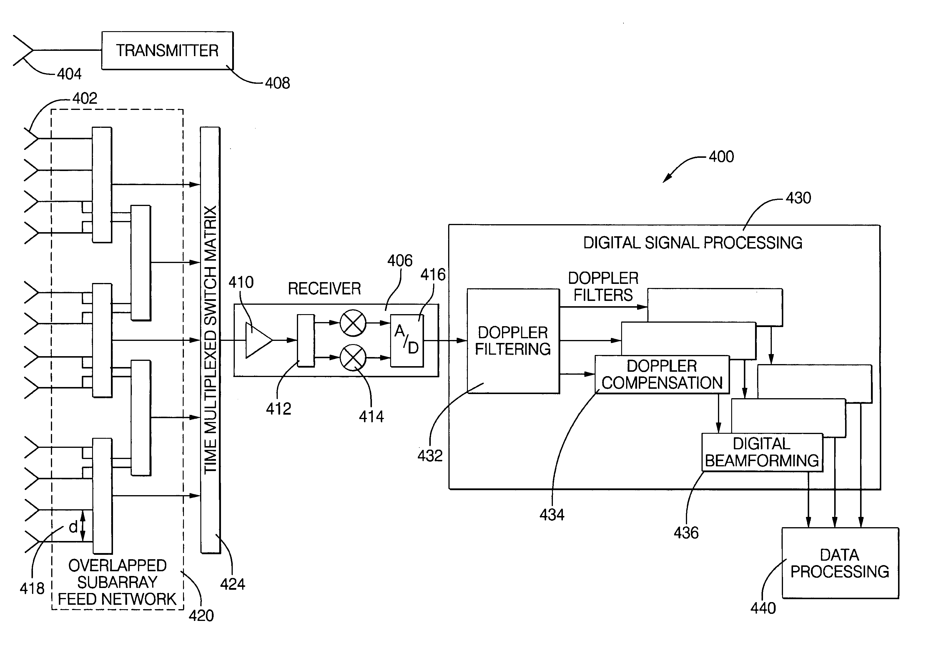
[0022] A system and method is described herein for providing a high performance and low cost electronically scanned radar system and method. The present invention can provide enhanced sensitivity, wide angle or field of view (FOV) coverage with narrow beams having high resolution, reduced number of receivers employed, reduced sidelobes, elimina...


PUM


Abstract

Digital beamforming is provided for use with electronically scanned radar. In an aspect, the present invention provides enhanced sensitivity, wide angle or field of view (FOV) coverage with narrow beams, minimized number of receivers, reduced sidelobes, eliminated grating lobes and beam compensation for target motion. In an aspect, the present invention employs a uniform overlapped subarray feed network, a time multiplexed switch matrix, and a restructured digital signal processor. Antenna channels share a receiver, rather than maintain a dedicated receiver for each antenna element, as in conventional systems. In an aspect, Doppler/frequency filtering is performed on each antenna element or subarray output prior to digital beamforming. Further, Doppler compensation is employed following Doppler/frequency filtering, followed by digital beamforming.

Description

FIELD OF THE INVENTION [0001] The invention relates generally to a high performance and low cost radar system, and more particularly to digital beamforming for use with electronically scanned radar. BACKGROUND OF THE INVENTION [0002] Numerous current radar systems, including automotive radar systems, require wide angle coverage having narrow beams and a high update rate, all in a small package size. Current automotive radar systems for applications including collision warning, pre-crash sensing and adaptive cruise control incorporate a fixed beam, switched beam or mechanically scanned antenna that limit performance by falling short of these previously mentioned requirements. In the case of mechanically scanned antennas, the update rate is too slow for current demands, system size and cost are high, and reliability is low. [0003] Electronically scanned antennas are also employed with radar systems. Allowing an antenna to electronically scan has benefits over a mechanically scanned an...

Claims


Application Information

Patent Timeline
IPC IPC(8): G01S7/28G01S13/93G01S13/931
CPCG01S7/288G01S7/352G01S13/52G01S13/931G01S2007/356G01S2007/358G01S2013/935H01Q21/0006H04B7/01G01S2013/9314G01S2013/9325G01S2013/9346G01S2013/0245G01S2013/9319G01S2013/93185G01S7/358G01S7/356
Inventor ALLAND, STEPHEN W.
Owner APTIV TECH LTD
Why Eureka
Try Eureka