Plasma processing apparatus and method for manufacturing thereof

a processing apparatus and plasma technology, applied in plasma techniques, electrical apparatus, electric discharge tubes, etc., can solve the problems of inferior processing and damage of workpieces, arc discharge is liable to drop, and the surface processing efficiency is not sufficient, so as to achieve the effect of preventing inferior processing and damage to workpieces and enhancing plasma surface processing efficiency

Inactive Publication Date: 2007-01-04
SEKISUI CHEM CO LTD
View PDF0 Cites 29 Cited by
  • Summary
  • Abstract
  • Description
  • Claims
  • Application Information

AI Technical Summary

Benefits of technology

[0052] In the elongated structure, it is desirous that a spacer composed of an insulating material is sandwiched between the respective end parts on the same side in the longitudinal direction of the pair of electrodes, and the conductive member is formed in such a manner as to keep away from the boundary between the spacer and the electrodes (see FIG. 12). Owing to this arrangement, when a surface discharge occurs at the boundary between the spacer and the electrode, the surface discharge can be prevented from conducting to the conductive member.
[0053] In the present invention, the electrode can be brought closer to the workpiece while preventing an arc discharge from occurring to the workpiece. Accord...

Problems solved by technology

Because of this reason, the ratio of deactivating the processing gas until the processing gas reaches the workpiece is increased and the surface processing efficiency is not sufficient.
On the other hand, in case the lower holder is excessively thin, an arc discharge is liable to drop onto the workpiece when the electrodes are brought closer to the workpiece, with a result that inferior processing and damage of t...

Method used


Image

  • Plasma processing apparatus and method for manufacturing thereof
  • Plasma processing apparatus and method for manufacturing thereof
  • Plasma processing apparatus and method for manufacturing thereof

Examples


first embodiment

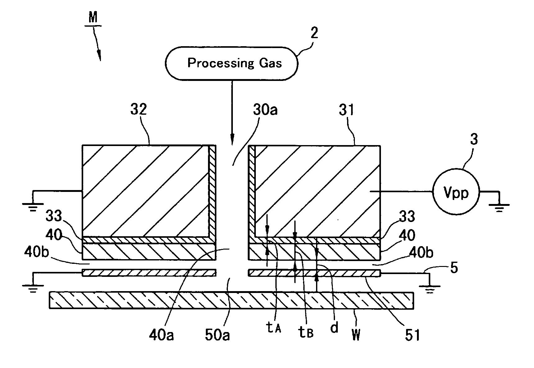
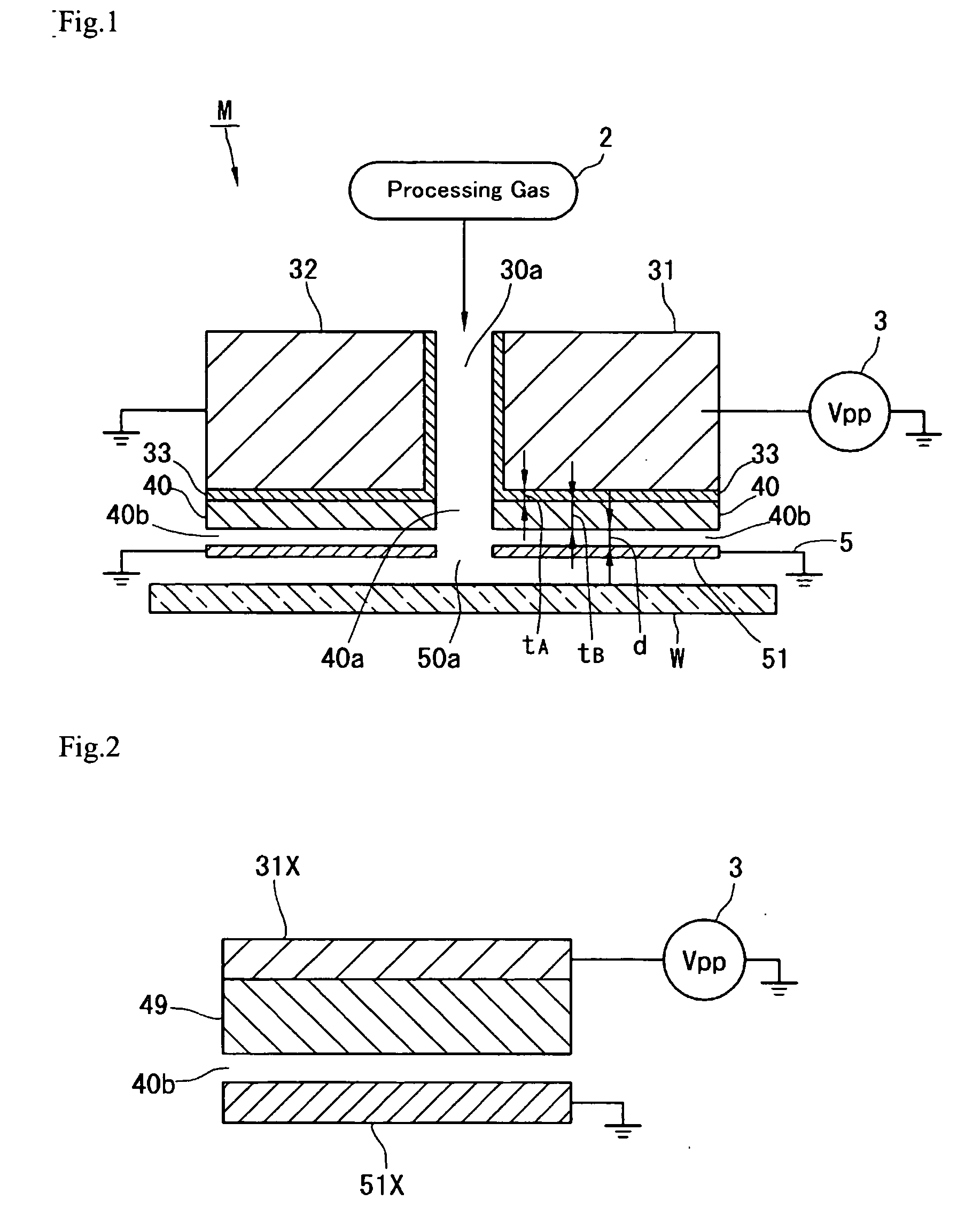
[0055] Embodiments of the present invention will be described hereinafter with reference to the drawings. A first embodiment will be described. FIG. 1 is a view schematically showing the construction of a normal pressure plasma processing apparatus. The normal pressure plasma processing apparatus M includes a pair of mutually opposing electrodes 31, 32. The electrode 31 is connected with a power source 3 as a voltage applying means and the remaining electrode 32 is grounded. Formed between the electrodes 31, 32 is a plasma generating space 30a. An electric field is applied to the plasma generating space 30a by the power source 3, thereby occurring a glow discharge. A processing gas fed from a processing gas source 2 is introduced into the plasma generating space 30a and plasmatized. The processing gas thus plasmatized is sprayed onto a workpiece W or an object to be processed located thereunder, through a jet port 40b as later described. By doing so, the workpiece W is subjected to ...

second embodiment

[0129] The second embodiment will be described with reference to FIGS. 10 through 12, next.

[0130] As shown in FIG. 10, a normal pressure plasma processing apparatus M2 according to the second embodiment comprises a processing gas source 2, a pulse source 3, a workpiece feed mechanism 4, a portal shaped frame 60 and a pair of left and right nozzle heads (processing head) 1. The processing gas source 2, the power source 3 and the feed mechanism 4 are same as in the apparatus M1 of FIGS. 4 through 6.

[0131] The portal shaped frame 60 includes left and right pedestrals 62, and is located above the feed mechanism 4. The portal shaped frame 60 has a hollow interior which constitutes an exhaust duct for the processed gas (including by-products generated by processing). That is, the interior of each pedestral 62 of the portal shaped frame 60 is partitioned into two inner and outer suction chambers 62a, 62b by a partition wall 64. Two inner and outer suction ports 63a, 63b, which are connect...

third embodiment

[0165] A normal pressure plasma processing apparatus M3 will be described next, with reference to FIGS. 21 and 22.

[0166] As shown in FIG. 21, the normal pressure plasma processing apparatus M3 is an apparatus for performing, for example, a plasma etching as a plasma surface processing. A processing gas source 2X of the apparatus M3 reserves, for example, CF4 or the like as a processing gas for plasma etching.

[0167] The apparatus M3 comprises a cylindrical nozzle head 70 instead of the elongate nozzle head 1. This cylindrical nozzle head 70 is supported on a mount table (not shown) with its axis directed upward and downward. A workpiece W′ to be etched is arranged under this nozzle head 70.

[0168] The cylindrical nozzle head 70 will be described in detail.

[0169] The cylindrical nozzle head 70 comprises a body with its axis directed upward and downward, an insulating holder 80 loaded within this body 71, and an electrode structure 30X. The body 71 has a three-stage cylindrical confi...


PUM


Abstract

A plasma processing apparatus is provided on the side to be directed to a workpiece W of electrodes 31, 32 with a conductive member 51 through an insulating member 41. The insulating member 41 is sandwiched between the electrodes 31, 32 and the conductive member 51. The dielectric constant and the thickness of the insulating member 41 are established such that the voltage applied to a gap 40b formed between the insulating member 41 and the conductive member 51 becomes smaller than the sparking voltage. Owing to this arrangement, electrical discharge can be prevented from occurring in the gap 40b and thus, the processing quality can be enhanced.

Description

TECHNICAL FIELD [0001] This invention relates to an apparatus for performing a surface processing operation such as cleaning, film depositing, etching, surface modification and the like by plasmatizing a processing gas and jetting the plasmatized gas onto an object to be processed, i.e., workpiece and more particularly to a so-called remote type plasma processing apparatus in which a workpiece is arranged outside a plasmatizing space. BACKGROUND ART [0002] The plasma processing apparatus can be classified largely into two types; a so-called direct control type in which a workpiece is arranged in a plasmatizing space between electrodes and a so-called remote type in which a workpiece is arranged outside a plasmatizing space. [0003] As one example of the remote type plasma processing apparatus, Patent Document 1 discloses an apparatus having a vertical planar configuration with a pair of electrodes arranged one on its right side and the other on its left side in an opposing relation. ...

Claims


Application Information

Patent Timeline
IPC IPC(8): H01L21/683
CPCH01J37/32357H05H1/24H01L21/67069H05H1/2406
Inventor HINO, MAMORUMAYUMI, SATOSHIITO, TAKUMIUEHARA, TSUYOSHIONO, TAKAYUKI
Owner SEKISUI CHEM CO LTD
Why Eureka
Try Eureka