
Dynamic allocation of bandwidth in a bidirectional optical transmission system

a transmission system and dynamic technology, applied in the field of optical transmission systems, can solve the problems of inefficiency of configuration in fig. 1, inability to adapt to changing traffic demands, and insufficient wavelengths

Inactive Publication Date: 2007-01-04
AMERICAN TELEPHONE & TELEGRAPH CO
View PDF43 Cites 26 Cited by
  • Summary
  • Abstract
  • Description
  • Claims
  • Application Information

AI Technical Summary

Benefits of technology

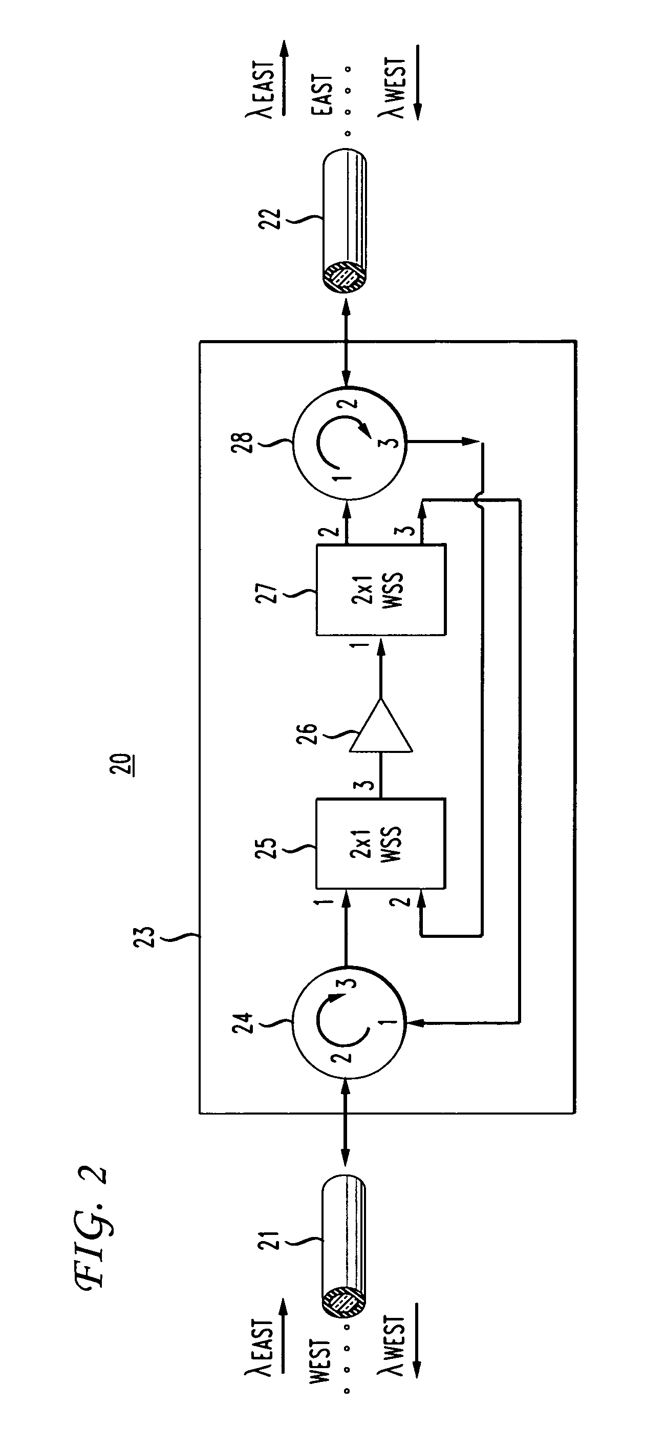
[0005] The present invention provides a bidirectional optical communications system that enables the allocation and reallocation of available wavelengths between the East and West directions in an optical fiber without the need for replacing optical components, such as fixed optical filters, and without the need to disturb or shut down communications on the fiber. This is accomplished by using programmable optical devices that are operable to dynamically allocate wavelengths between the East and West directions in the bidirectional optical fiber, as needed. As used herein, the term dynamic allocation refers to the ability to allocate and reallocate wavelengths between the East and West directions in a bidirectional optical fiber without the need to replace optical components, such as fixed optical filters, and without the need to disrupt communications on the wavelengths that are not being reallocated. As used herein, the term programmable optical component refers to subsystems which can be controlled from a signal sent from outside the optical component. For example, the signal can be an electrical digital signal generated from a computer.
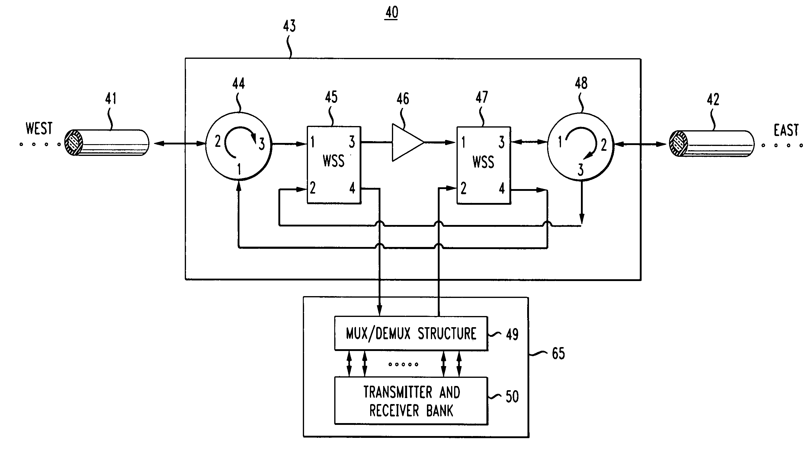
[0009] In yet another embodiment of the invention, a programmable optical component composed of two 2×2 wavelength selective switches, two optical circulators, and one gain block, is combined with a mux / demux structure and a transmitter and receiver bank. The mux / demux structure and the transmitter and receiver bank operate as an add / drop multiplexer that enables wavelengths to be dynamically added to and removed from the bidirectional optical fiber as traffic needs change. Thus, such an embodiment not only provides the ability to dynamically allocate wavelengths between East and West in a bidirectional optical fiber, but it also provides the ability to dynamically add and remove wavelengths as needed.

Problems solved by technology

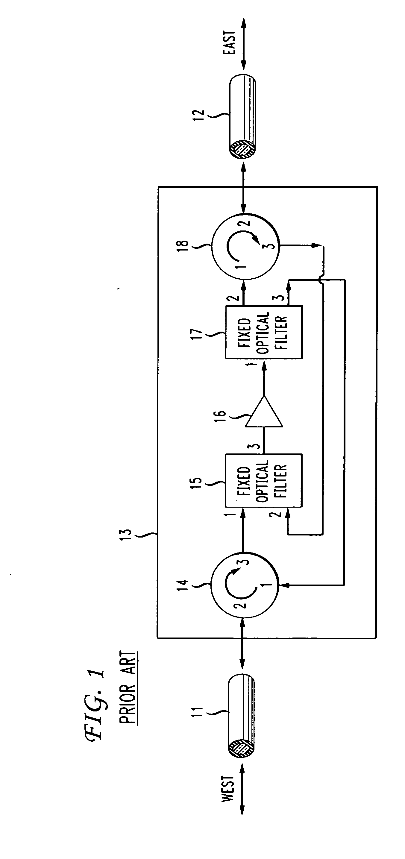
However, in systems in which the traffic demands are asymmetric, the configuration in FIG. 1 is not efficient.
Asymmetric traffic flow could cause the system of FIG. 1 to not have enough wavelengths to carry information in the busy direction while, at the same time, have unused wavelengths allocated to the other direction.
In addition, the configuration of FIG. 1 cannot adapt to changing traffic demands.
Replacing fixed optical filters 15 and 17 each time a reallocation is needed would not only be costly but would disturb or shut down the entire system (i.e. communications on every wavelength λ1-n) every time the filters were replaced.

Method used


Image

  • Dynamic allocation of bandwidth in a bidirectional optical transmission system
  • Dynamic allocation of bandwidth in a bidirectional optical transmission system
  • Dynamic allocation of bandwidth in a bidirectional optical transmission system

Examples


Embodiment Construction

[0017]FIG. 2 shows an embodiment of a bidirectional communications system 20 in accordance with the present invention. As shown, a programmable optical component 23 is coupled to a bidirectional optical fiber 21 and a bidirectional optical fiber 22. Bidirectional optical fiber 21 is operable to transmit a set of available wavelengths λ1 . . . n to and from a West direction, and bidirectional optical fiber 22 is operable to transmit a set of available wavelengths λ1 . . . n to and from an East direction. Programmable optical component 23 has an optical circulator 24, a 2×1 wavelength selective switch 25, a gain block 26, a 1×2 wavelength selective switch 27, and an optical circulator 28, all known devices in the art. Gain block 26 may be an erbium doped fiber amplifier or any other amplifier known in the art.

[0018] Wavelengths traveling from West to East, λEast, on bidirectional optical fiber 21 will enter programmable optical component 23 and be input to port 2 of optical circulato...


PUM


Abstract

A bidirectional optical communications system that is operable to dynamically allocate wavelengths for transmission in either direction in an optical fiber. The dynamic allocation is controlled by programmable optical devices. The programmable optical devices may be well known programmable devices such as wavelength selective switches and wavelength blockers or any other programmable optical device capable of dynamically allocating wavelengths between the two directions in the optical fiber. In addition, the programmable optical devices may be any combination of such wavelength selective switches, wavelength blockers or other programmable optical devices with other optical devices such as optical circulators, gain blocks, add / drop multiplexers, or fixed optical filters. Such a bidirectional optical communications system enables the dynamic allocation of bandwidth in an optical fiber without the need to replace components, such as fixed optical filters, and without disturbing communications on all the wavelengths transmitted in the optical fiber.

Description

BACKGROUND OF THE INVENTION [0001] The present invention is directed to an optical transmission system. More specifically, the present invention is directed to a bidirectional optical transmission system in which bandwidth can be dynamically allocated to transmit information in either direction in an optical fiber. [0002] It is known how to provide bidirectional optical communications in a single optical fiber. Today, single-fiber bidirectional optical transmission systems generally offer information transfer capacity wherein the wavelengths used to carry information in a given direction through the fiber are fixed and symmetric. That is, half the wavelength channels are permanently assigned, or fixed, to carry information in one direction through the fiber, and half the wavelength channels are permanently assigned to carry information in the other direction through the fiber. [0003] An example of one such known configuration is illustrated in FIG. 1. As shown, a bidirectional optic...

Claims


Application Information

Patent Timeline
IPC IPC(8): H04J14/02H04L69/14
CPCH04B10/2503H04J14/0212H04J14/0213H04J14/025H04J14/0226H04J14/0246H04J14/0216H04B10/2589
Inventor FEUER, MARK DAVIDWOODWARD, SHERYL LEIGH
Owner AMERICAN TELEPHONE & TELEGRAPH CO
Learn More