Radio lan antenna

a radio lan and microstrip technology, applied in the direction of resonant antennas, individually energised antenna arrays, waveguides, etc., can solve the problems of reducing the transmission loss of wireless-communication rf signals in the transmission line, reducing the possibility of interference with or being interfered by radio waves of other antennas, and increasing the communication distan

Inactive Publication Date: 2007-01-04
KOBE STEEL LTD
View PDF7 Cites 70 Cited by
  • Summary
  • Abstract
  • Description
  • Claims
  • Application Information

AI Technical Summary

Benefits of technology

[0113] Further, by giving directivity to the radio antenna described above, it is possible to compensate for attenuation of radio waves and to increase the communication distance. In addition, a possibility of interfering with or being interfered by radio waves of other antennas can be reduced.
[0114] As described above, the wireless-communication RF signal transmission device according to the present invention, when there are a plurality of transmission lines, RF signals for wireless communication can be prevented from attenuating due to an increase in total distance of the transmission lines by installing a radio antenna between the transmission lines. This advantage can also be obtained between the higher-level unit and the transmission line.
[0115] According to another aspect of the present invention, the frequency of the wireless-communication RF signal in the transmission line (i.e., the transmission line frequency) can be made different from the frequency of the wireless-communication RF signal transmitted from and received by the radio antenna (i.e., the radio frequency). By setting the transmission line frequency to be lower than the radio frequency, therefore, a transmission loss of the wireless-communication RF signal in the transmission line can be suppressed. Hence, the length of the transmission line can be drastically increased in comparison with the case where the radio frequency is the same as the transmission line frequency as in the known system.
[0116] Further, it is possible to not only optionally set combinations of the transmission line frequency and the radio frequency which are used in a plurality of branch sections (communication-wave branching / joining sections) in the transmission line, but also to set the number of (kinds) of transmission line frequencies used to be larger than the number of (kinds) of radio frequencies used. As a result, regardless of the number of (kinds) of radio frequencies which are subjected to large limitations on usable bands, RF signals for wireless communication containing many signals (channel signals) of different transmission line frequencies in superimposed relation can be propagated through the communication line so that signal collisions can be avoided and a drastic increase of signal transmission capacity of the transmission line can be obtained. Furthermore, radio communication environments can be more flexibly designed in points such as setting the radio frequency to differ from each other between the radio antennas in adjacent areas, to thereby prevent interference between electric waves, or allocating separate higher-level units (master units) having different transmission line frequencies from each other corresponding to the individual branch sections (radio communication areas).
[0117] Additionally, by regulating the transmitting directions of down- and up-RF signals for wireless communication with a circulator or a switch, the RF signals for wireless communication are prevented from creeping and forming a loop between the down-side and the up-side, and communication quality can be maintained.

Problems solved by technology

However, because the tubular waveguide and the coaxial cable used as high-frequency lines have relatively large sectional areas and volumes in themselves, they require a relatively large space when installed.
Furthermore, time, labor and an overall cost including an installation cost are increased in proportion to the length of high-frequency lines required in the area.
Providing the branch circuits on the tubular waveguide or the coaxial cable, however, also pushes up the overall cost to such an extent as comparable to the installation of the high-frequency line itself.
Thus, in situations up to now, the above-described restrictions in the known structures of high-frequency lines have posed limitations in installing and employing the wireless LAN system in target places or various local areas, thereby causing serious limitations in increasing applications of the wireless LAN system.
However, that known strip-like high-frequency line has no flexibility and cannot be in itself freely deformed depending on the intention in use.
Further, handling of the known strip-like high-frequency line, such as required in the installation work and transportation to the installation place, is also troublesome.
However, because of having the sectional structure in which the dielectric layer is sandwiched by the pair of ground layers and the signal line is disposed in the dielectric layer, the proposed high-frequency line has a problem that a relatively short line can be manufactured inexpensively, but the cost in manufacturing a relatively long line is increased with a current level of manufacturing techniques.
With a current level of manufacturing techniques, however, a limit of the length within which the line can be manufactured inexpensively is about 2 m.
This gives rise to problems in practical use, such as a leakage and loss of the high-frequency wave at joints, troublesome work required in splicing the lines, and so on.
Accordingly, in spite of the proposed high-frequency line employing the patch antenna, another problem arises in that troublesome work for opening and closing the openings without a leakage of the high-frequency wave is required depending on change of the branch circuits.
If the multi-path fading occurs, the high-frequency waves transmitted from adjacent antenna units and each propagating in a concentric pattern cancel each other completely, thus resulting in a communication error.
Depending on the position (place) of the wireless LAN mobile station (terminal), data communication is difficult to perform.
However, the polarization diversity transmission system has a problem of difficulty in carrying out high bit-rate communication due to increased reflections of electric waves in an environment where the distance between the base station antenna and the mobile station terminal antenna is increased (farther away) over, e.g., 10 m. In other words, a larger distance between the two antennas increases a probability that the number of objects interfering visibility between the two antennas and the number of metal-made structures tending to reflect the electric waves are increased, for example, as in the interior of a factory building described later with reference to FIG. 42.
Eventually, a reception S / N is reduced and high bit-rate communication is difficult to perform.
Also, in the case using linearly polarized waves in the polarization diversity transmission system, if good visibility is not given between the base station antenna and the mobile station terminal antenna, electric waves received via multiple paths through reflections are apt to interfere with each other.
As a result, a reception S / N is reduced and high bit-rate communication is difficult to realize.
Accordingly, when the circular polarized antennas are used in the wireless LAN base station side, there inevitably occurs the above-mentioned problem of a reduction in reception power.
Further, the dipole antenna has a problem that directivity is weak and the influence of the multi-path fading is noticeable particularly in the up-direction toward the wireless LAN base station antenna from the terminal side antenna.
This leads inevitably to that, depending on positions of the wireless LAN mobile station terminals, some terminals can receive the circularly polarized waves in some positions, but the other terminals cannot receive them.
Also, there is a tendency that, depending on attitudes (bearings and directions) of the circular polarized antennas in the mobile station terminal side, some antennas can transmit and receive the circularly polarized waves at a high level, but the other antennas cannot transmit and receive them at a high level.
Still another problem is that the mobile station terminal side has no means for selecting the best one, as a transmitting and receiving antenna, from among a plurality of antennas disposed in the wireless LAN base station, and it is difficult to select the best antenna in the base station side from the mobile station terminal side.
Looking at the case of an indoor wireless LAN system as an example, there are usually many obstacles against electromagnetic waves propagating between the master unit and the slave units of the wireless LAN in an indoor space, such as desks, racks, partitions, and business machines.
As a result, a data error rate is so increased as to repeat transmitting, thus resulting in a lower effective communication bit rate.
Also, even when good visibility is ensured with no obstacles against electromagnetic waves, there is a problem that, due to influences of reflected electromagnetic waves from wall surfaces, a ceiling surface, a floor surface, office fixtures, business machines, etc., the SN ratio cannot be obtained at a level enough to demodulate the transmitted data and the communication bit rate is lowered.
Those problems may similarly occur in the wireless LAN system installed in a certain area other than the indoor space.
That requirement raises a problem that, because the attenuation rate of a high-frequency signal (RF signal for wireless communication) in the transmission line is generally increased at a higher frequency, the length of the transmission line cannot be set to a sufficiently large value.
Such an increase in the number of units used leads to problems of an increased amount of time and labor required for installation, an increase of energy consumption, and hence an increased system cost.
Although the related art can also connect the plurality of master units to the transmission line, there is a problem that, because the transmission line frequency and the radio frequency correspond to each other in 1:1 relation, the number of waves (signals) capable of being multiplexed in the transmission line is limited to the number of waves which are permitted for use as the radio frequency, thus resulting in a greater limitation.
Accordingly, it is impossible to realize flexible design of communication environments, for example, by assigning the wireless LAN master unit (higher-level unit) corresponding to each area where the branch circuit is disposed, for the purpose of efficiently distributing the communication load.
However, laying a single long transmission line so as to penetrate a plurality of rooms partitioned by walls requires a great deal of work cost, particularly in the case of the walls being made of, e.g., reinforced concrete, even if the work of penetrating the walls is physically feasible.
Also, in the case of, e.g., an office of a tenant borrowing one or more rooms of a building, the work of penetrating walls cannot be usually performed unless such work is approved by the owner of the building.
Looking at, as another example, the case laying a wireless-communication RF signal transmission line in cars of a railway train, it is very difficult to lay the wireless-communication RF signal transmission line bridging between the cars composing the train.
Although newly manufactured cars can be designed so as to bury such flexible cables therein, it is generally quite difficult to additionally install those flexible cables in existing cars, including design to secure cable routes.
Further, since the train composition is changed day by day in many cases, the use of the flexible cables to extend the wireless-communication RF signal transmission line is inconvenient with the necessity of work for disconnecting the flexible cables and connecting them again whenever the train composition is changed.

Method used


Image

  • Radio lan antenna
  • Radio lan antenna
  • Radio lan antenna

Examples


first embodiment

of Wireless-Communication RF Signal Transmission Device

[0376] A wireless-communication RF signal transmission device X1 according to a first embodiment of the present invention will be described below. The wireless-communication RF signal transmission device X1 is one resulting from modifying the frequency conversion circuit 252 into another arrangement. The remaining arrangement and functions are the same as those in the wireless-communication RF signal transmission device X. In the following, a frequency conversion circuit 81 included in the wireless-communication RF signal transmission device X1 is described with reference to FIG. 47.

[0377] The frequency conversion circuit 81 comprises a down-side frequency conversion circuit 81a (one example of the frequency downconversion means) for executing frequency conversion of the down-signal (wireless-communication RF signal flowing downstream), an up-side frequency conversion circuit 81b (one example of the frequency upconversion means...

second embodiment

of Wireless-Communication RF Signal Transmission Device

[0387] A wireless-communication RF signal transmission device X2 according to a second embodiment of the present invention will be described below. The wireless-communication RF signal transmission device X2 is one resulting from replacing a part of the frequency conversion circuit 252 in the wireless-communication RF signal transmission device X with other components. The remaining arrangement and functions are the same as those in the wireless-communication RF signal transmission device X. In the following, features of the wireless-communication RF signal transmission device X2 differing from the wireless-communication RF signal transmission device X are described with reference to FIG. 48.

[0388] In the wireless-communication RF signal transmission device X2, as shown in FIG. 48, the distributors 252c, 252d in the frequency conversion circuit 252 of the wireless-communication RF signal transmission device X are replaced with ...

third embodiment

of Wireless-Communication RF Signal Transmission Device

[0395] A wireless-communication RF signal transmission device X3 according to a third embodiment will be described below. The wireless-communication RF signal transmission device X3 is one resulting from replacing a part of the frequency conversion circuit 252 in the wireless-communication RF signal transmission device X with other components. The remaining arrangement and functions are the same as those in the wireless-communication RF signal transmission device X. In the following, features of the wireless-communication RF signal transmission device X3 differing from the wireless-communication RF signal transmission device X are described with reference to FIG. 49.

[0396] In the wireless-communication RF signal transmission device X3, as shown in FIG. 49, the distributors 252c, 252d in the frequency conversion circuit 252 of the wireless-communication RF signal transmission device X are replaced with a switch 83c in the transm...


PUM


Abstract

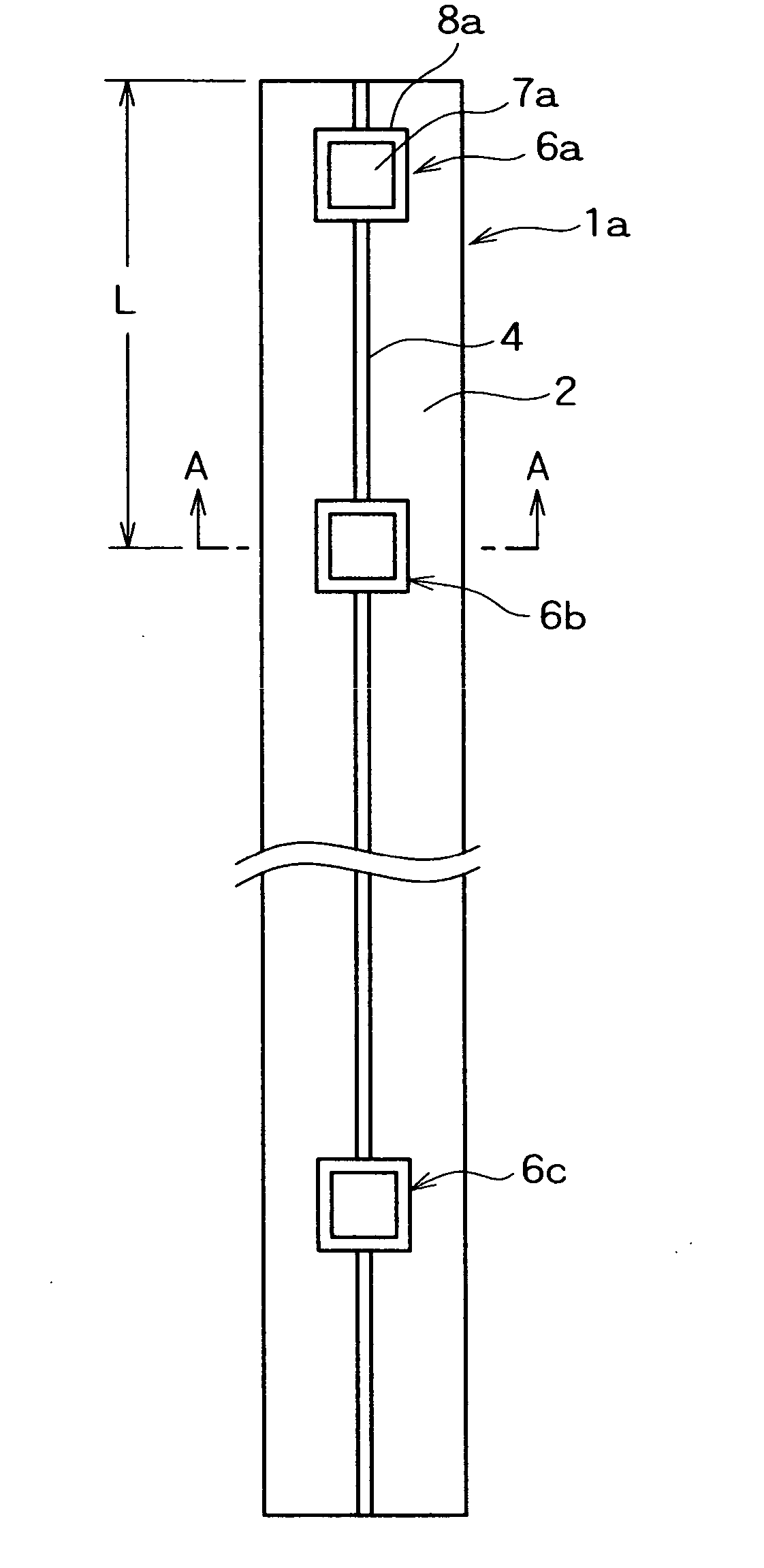
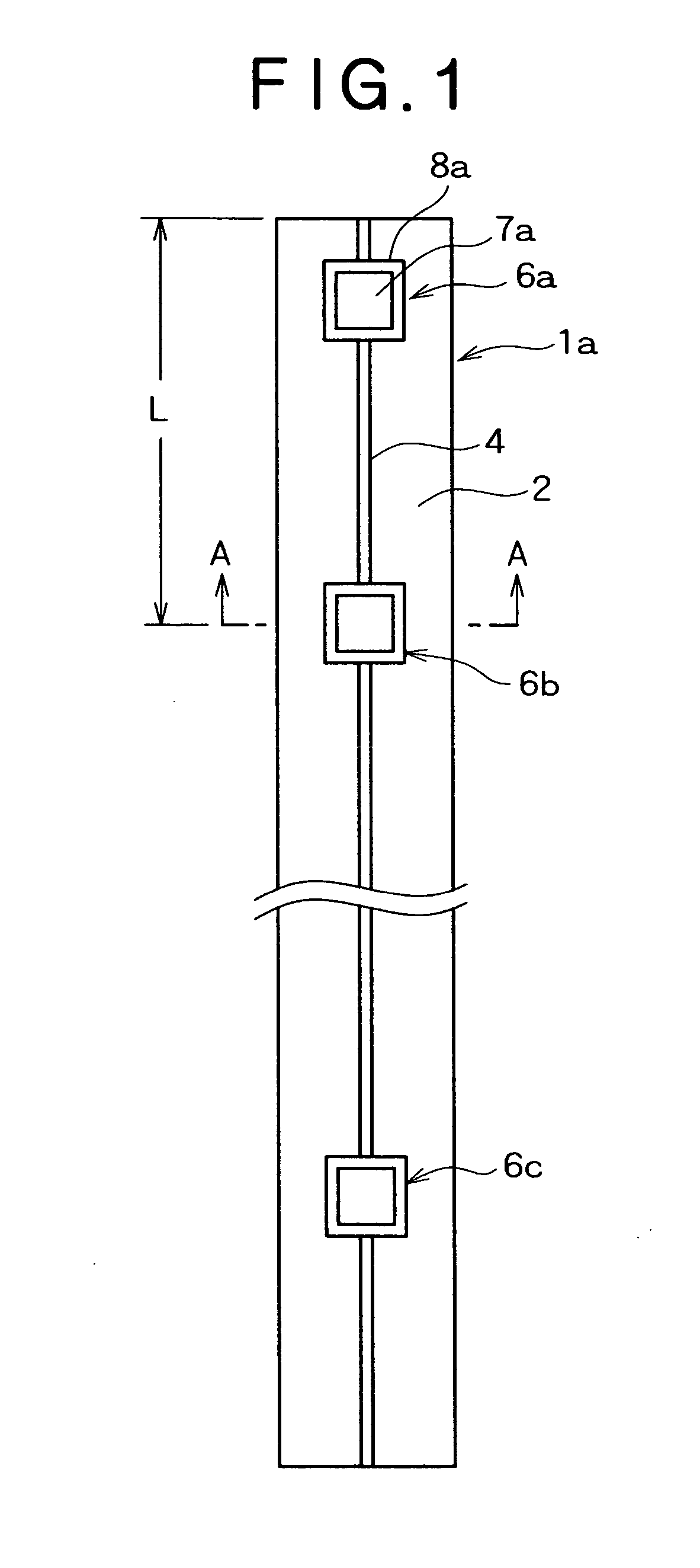
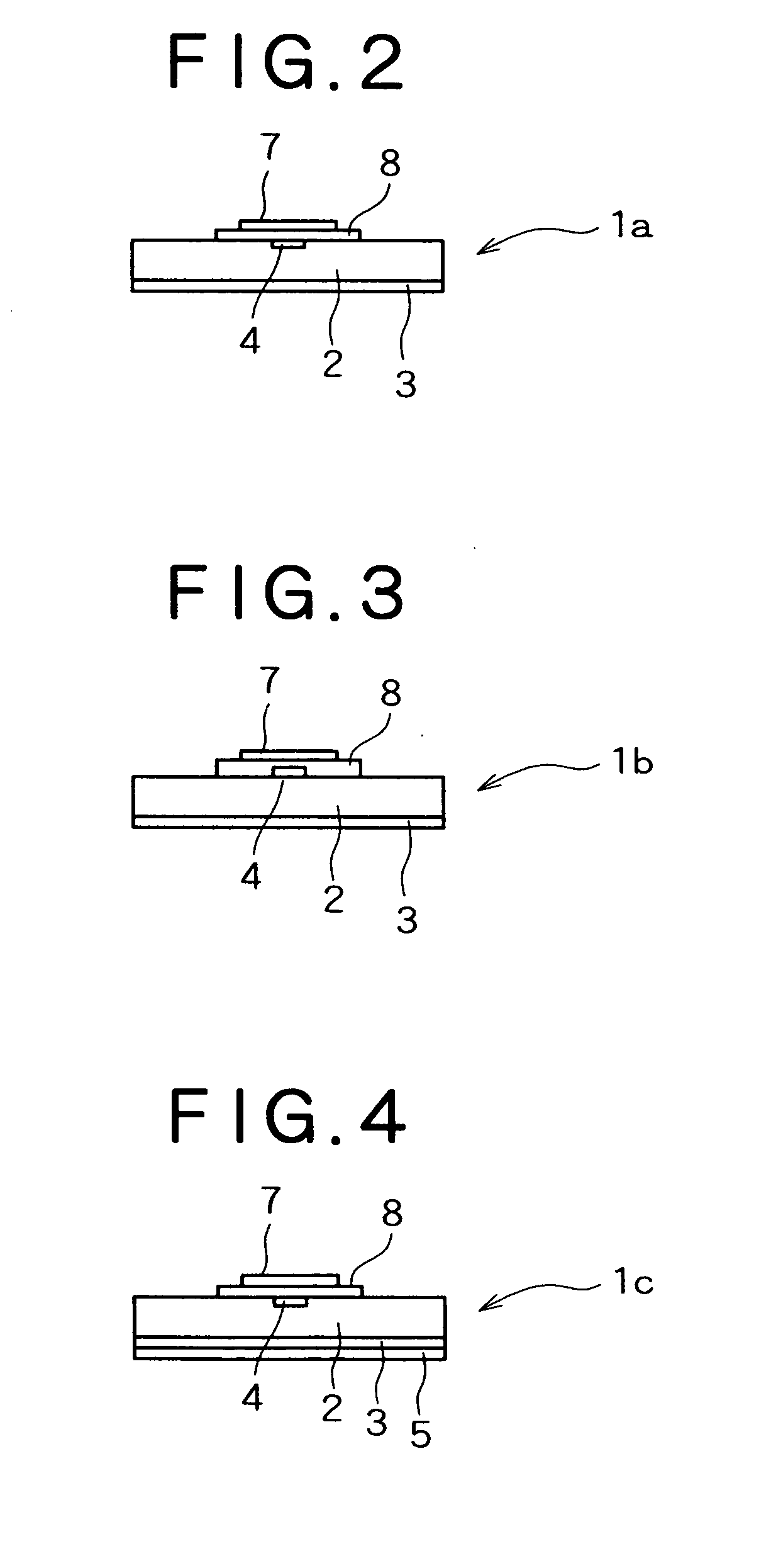
A high-frequency micro-strip line for transmitting a high-frequency wave for a wireless LAN system has a layered structure where, on a ground layer made of a conductive material, a dielectric layer made of a dielectric material and a signal line made of a conductive material are successively laid. The high-frequency micro-strip line further includes a patch antenna comprising a dielectric plate made of a dielectric material and a patch made of a conductive material, which are successively laid into a layered structure, the patch antenna being electrically connected to the signal line. A wireless-communication RF signal transmission device capable of being applied to such a line is also provided.

Description

TECHNICAL FIELD [0001] The present invention relates to a high-frequency micro-strip line, a wireless LAN mobile-station terminal antenna, a wireless LAN card for a terminal, a wireless LAN system, and a wireless-communication RF signal transmission device, which are applied to a wireless LAN system forming a radio communication network and are used for propagating signals of high-frequency electromagnetic waves in a radio frequency band (hereinafter also referred to simply as “electromagnetic waves” or “high-frequency waves”). BACKGROUND ART [0002] Recently, with the progress toward more advanced information society, a wireless LAN (Local Area Network) system forming a radio communication network in a certain area has been increasingly used in various fields including not only indoor uses, e.g., offices in buildings etc., factories, warehouses and other yards, as well as general houses and business premises, but also uses other than the indoor uses, such as arcades in shopping dist...

Claims


Application Information

Patent Timeline
Patent Type & Authority Applications(United States)
IPC IPC(8): H04B1/06H04B1/38H04B7/00H01Q1/00H01Q1/27H01Q9/04H01Q13/08H01Q13/20H01Q21/08H01Q21/20H04L12/28
CPCH01Q1/007H01Q1/276H01Q9/0407H04W84/12H01Q21/08H01Q21/20H01Q13/206H01P1/10H01Q13/08H01P5/00H01P3/08
Inventor KUSAKA, TAKUYAMARUYAMA, MASAKATSUMANABE, CHITAKAFUKUMOTO, YOSHITOTAMURA, NAOKI
Owner KOBE STEEL LTD
Why Eureka
Try Eureka