Mixing chamber

a technology of mixing chamber and mixing chamber, which is applied in the direction of liquid degasification, membranes, separation processes, etc., can solve the problems of large energy consumption, limited fluid transfer in this approach to the effect of the gas lifting mechanism, and high capital and operating costs, so as to reduce the anoxic zone, improve the quality of the filtrate, and reduce the residence time

Active Publication Date: 2007-01-11
EVOQUA WATER TECH LLC
View PDF98 Cites 117 Cited by
  • Summary
  • Abstract
  • Description
  • Claims
  • Application Information

AI Technical Summary

Benefits of technology

[0046] If required, a further source of aeration may be provided within the tank to assist microorganism activity and to reduce anoxic zone. For preference, the membrane module is suspended vertically within the tank and said further source of aeration may be provided beneath the suspended module. Preferably, the further source of aeration comprises a group of air permeable tubes or discs. The membrane module may be operated with or without backwash depending on the flux. A high mixed liquor of suspended solids (5,000 to 20,000 ppm) in the b

Problems solved by technology

However, the capital and operating cost can be prohibitive.
The fluid transfer in this approach is limited to the effectiveness of the gas lifting mechanism.
However, this method has several disadvantages: it consumes large amounts of energy, possibly forms mist or froth flow reducing effective membrane filtration area, and may be destructive to membranes.
Moreover, in an envi

Method used


Image

  • Mixing chamber
  • Mixing chamber
  • Mixing chamber

Examples


Embodiment Construction

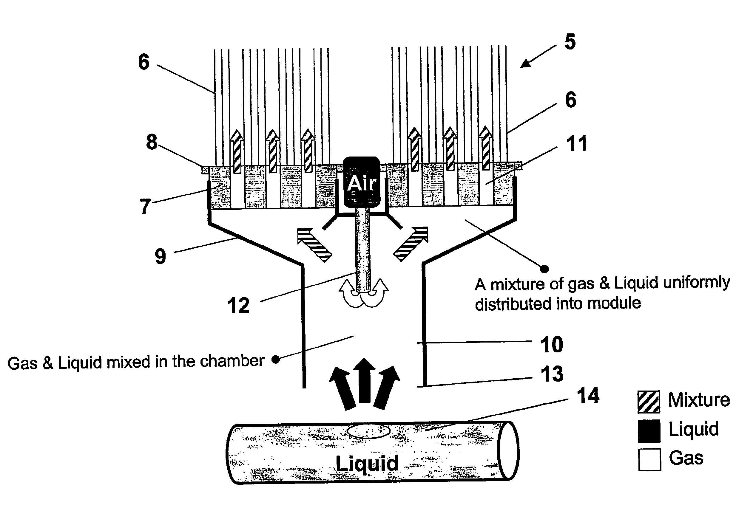
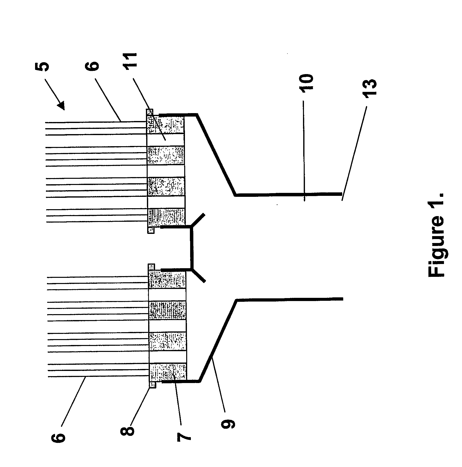
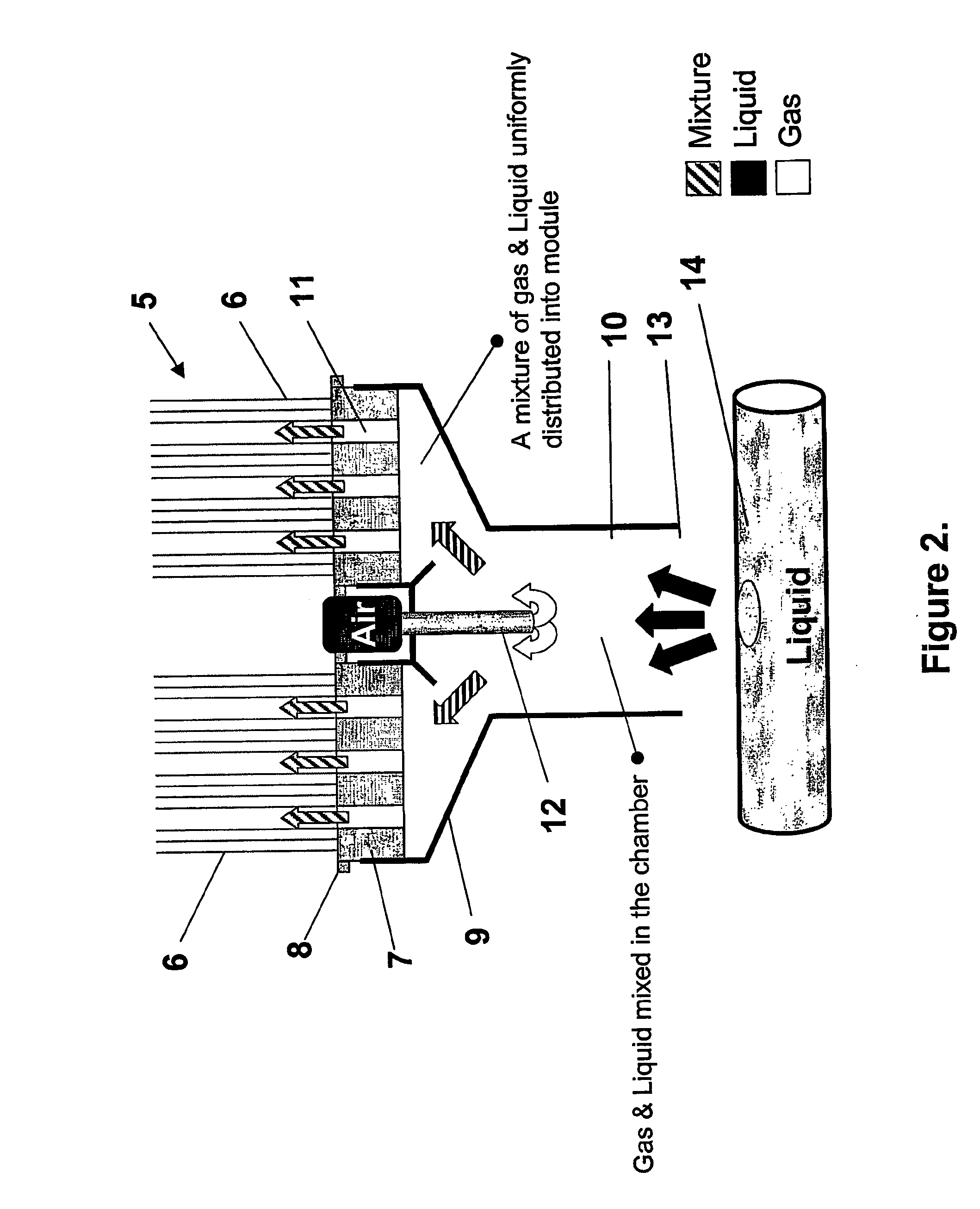
[0058] Referring to the drawings, the embodiments of the invention will be described in relation to a membrane module of the type disclosed in our earlier PCT application Nos. WO98 / 28066 and WO00 / 18498 which are incorporated herein by cross-reference, however, it will be appreciated that the invention is equally applicable to other forms of membrane module.

[0059] As shown in FIG. 1, the membrane module 5 typically comprises fibre, tubular or flat sheet form membranes 6 potted into a pot 7 which is supported by a header 8. The membranes are typically encased in a support structure (not shown). In the embodiment shown, the headers 8 are coupled to a clover type manifold 9 which in turn is connected to an open ended elongate chamber 10 positioned below the manifold 9. The membrane module is typically immersed in a feed tank and either one or both ends of the membranes may be used for the permeate collection. The bottom of each membrane module 5 has a number of through apertures 11 in ...


PUM

PropertyMeasurementUnit
Fractionaaaaaaaaaa
Fractionaaaaaaaaaa
Diameteraaaaaaaaaa

Abstract

A membrane module (5) including a plurality of porous membranes (6) extending in an array and mounted, at least at one end, in a header (8). The header (8) has a number of distribution apertures (11) for distributing a fluid into the module (5) and along a surface or surfaces of the membranes (6). An elongate chamber (10) having one open end (13) and another end is in fluid communication with the distribution apertures (11) for distributing the fluid to the distribution apertures (11).

Description

TECHNICAL FIELD [0001] The present invention relates to apparatus and related methods for use of a chamber in association with membrane filtration modules to provide improved fluid distribution and flow into the associated modules. BACKGROUND OF THE INVENTION [0002] The importance of membranes for treatment of waste water is growing rapidly. It is now well known that membrane processes can be used as an effective tertiary treatment of sewage and provide quality effluent. However, the capital and operating cost can be prohibitive. With the arrival of submerged membrane processes where the membrane modules are immersed in a large feed tank and filtrate is collected through suction applied to the filtrate side of the membrane, membrane bioreactors combining biological and physical processes in one stage promise to be more compact, efficient and economic. Due to their versatility, the size of membrane bioreactors can range from household (such as septic tank systems) to the community an...

Claims


Application Information

Patent Timeline
IPC IPC(8): B01D17/035B01D19/00B01D61/18B01D63/02B01D63/04B01D65/02B01D65/08C02F3/12
CPCB01D61/18B01D63/02B01D63/024B01D63/04B01D65/02B01D2315/06B01D2321/04B01D2321/185B01D2313/105B01D2313/32B01D65/08
Inventor ZHA, FUFANGPHELPS, ROGER WILLIAMBROIS, ETIENNE ULYSSE
Owner EVOQUA WATER TECH LLC
Why Eureka
Try Eureka