

Optical device, light-condensing backlight system, and liquid crystal display
a backlight system and optics technology, applied in optics, polarising elements, instruments, etc., can solve the problems of increasing the number of parts, reducing the efficiency of light condensation, so as to reduce the coloration and reduce the effect of selective reflection wavelength and short selective reflection wavelength
- Summary
- Abstract
- Description
- Claims
- Application Information
AI Technical Summary
Benefits of technology
Problems solved by technology
Method used
Image

Examples
example 1
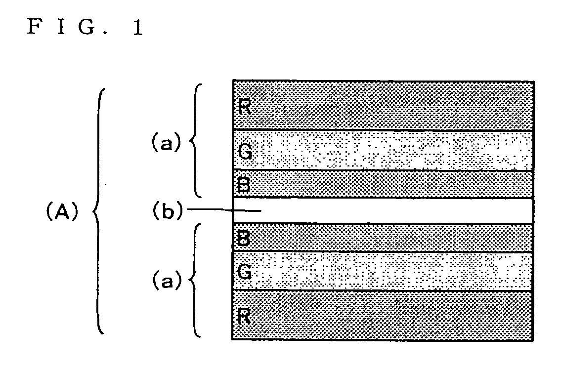
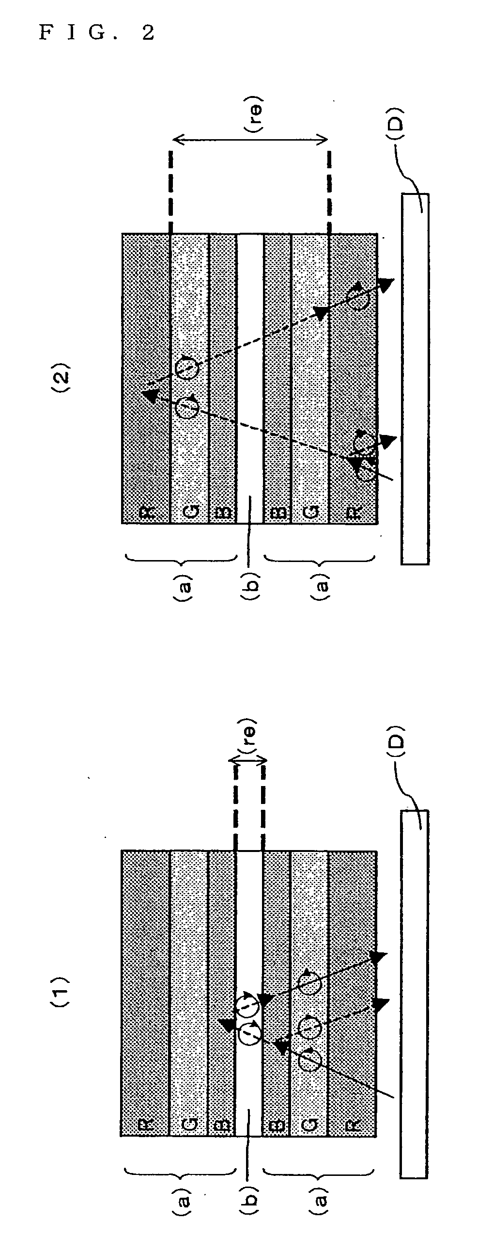
(Circular-Polarization-Type-Reflection Polarizer (a))
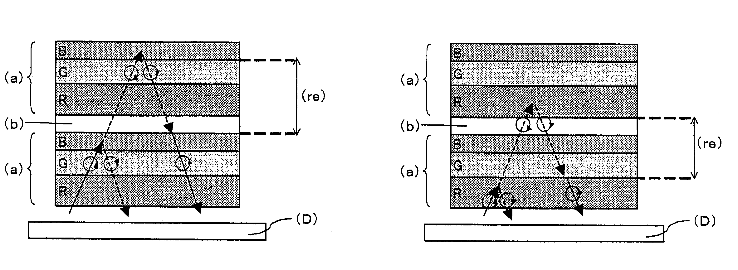
[0131] The circular-polarization-type-reflection polarizer (a) used was a laminate of cholesteric liquid crystal layers having selective reflection wavelength bands with central wavelengths of 400 nm, 550 nm and 630 nm, respectively, arranged in this order. The cholesteric liquid crystal layers had thicknesses of 1 μm, 1.2 μm and 1.3 μm, respectively, in this order.
(Retardation Layer (b))
[0132] A photopolymerizable nematic liquid crystal monomer (LC242 manufactured by BASF Ltd.), a chiral agent (LC756 manufactured by BASF Ltd.), a photoinitiator (Irgacure 907 manufactured by Ciba Specialty Chemicals Inc.), and a solvent (toluene) were prepared and mixed to form a coating liquid for providing a center wavelength of 350 nm for selective reflection. The coating liquid was applied to a commercially available polyethylene terephthalate film with a wire bar so as to provide a post-drying coating thickness of 4 μm, and then the solv...
example 2
(Circular-Polarization-Type-Reflection Polarizer (a))
[0137] The circular-polarization-type-reflection polarizer (a) used was a broadband cholesteric liquid crystal layer that had a reflection wavelength band ranging from 400 to 800 nm, continuously varying pitch lengths and a thickness of 6 μm.
(C-Plate Layer)
[0138] The same C-plate layer as in Example 1 was used.
(Optical Element (A))
[0139] A first piece of the circular-polarization-type-reflection polarizer (a) was placed on the backlight side in such a manner that its side having a selective reflection wavelength band on the long wavelength side (its side on which the cholesteric liquid crystal had a relatively long spiral pitch length) faced downward. Two pieces of the C-plate were laminated thereon via a 5 μm-thick adhesive so as to provide a retardation of 440 nm in the thickness direction. The laminate of the two pieces of the C-plate had a retardation of 70 nm, which was a measurement with respect to incident light inc...
example 3
(Circular-Polarization-Type-Reflection Polarizer (a))
[0143] The same circular-polarization-type-reflection polarizer (a) as in Example 2 was used.
(C-Plate Layer)
[0144] A transparent polyimide (6FDA-TFMD) was dissolved in a solvent, and the resulting solution was applied to a substrate so as to provide a post-drying thickness of 10 μm. The solvent was then dried off so that a C-plate layer (negative) was obtained. With respect to light with a wavelength of 550 nm, the retardation of the C-plate was measured to be 2 nm in the front direction and to be 400 nm in the thickness direction. When the incident light was inclined by 30°, the retardation was measured to be 60 nm.
(Optical Element (A))
[0145] A first piece of the circular-polarization-type-reflection polarizer (a) was placed on the backlight side in such a manner that its side having a selective reflection wavelength band on the long wavelength side (its side on which the cholesteric liquid crystal had a relatively long s...
PUM
| Property | Measurement | Unit |
|---|---|---|
| wavelength range | aaaaa | aaaaa |
| wavelength range | aaaaa | aaaaa |
| total thickness | aaaaa | aaaaa |
Abstract
Description
Claims
Application Information