Sintered sliding material, sliding member, connection device and device provided with sliding member

Inactive Publication Date: 2007-01-11
KOMATSU LTD
View PDF9 Cites 39 Cited by
  • Summary
  • Abstract
  • Description
  • Claims
  • Application Information

AI Technical Summary

Benefits of technology

[0053] As described above, the present invention can provide a sintered sliding material, a sliding member and a connecting device capable of demonstrating excellent seizing resistance and abrasion resistance under bad lubricating conditions such as a high-bearing stress and slow-speed sliding condition

Problems solved by technology

The sliding bearing can be used under a severe condition of a slow speed (0.6 m/min or less) and a high bearing stress up to 1200 kgf/cm2, while a conventional sliding material having an iron-carbon based alloy substrate cannot withstand such a severe condition.
Especially, under a condition of a significantly slow-speed and a high-bearing stress, release of hydraulic pressure through pores of the sintered material makes a thickness of a lubricating oil film formed on a bearing surface (a sliding surface) thin as roughness of the bearing surface or thinner, causing a boundary lubricating sliding condition accompanied with solid friction (adhesion) in many cases.
In view of the aforesaid composite sintered alloy material, which is made such that a composite sintered alloy composed of Cu powder and iron powder is subjected to a surface treatment such as a carburizing treatment and a nitriding treatment, according to the patent literature 1, and the aforesaid Fe-based sintered alloy material containing an extreme-pressure additive and the like filled in its pores and having a martensite structure, according to the patent literature 2, each has a problem in which sufficient sliding performance may not be demonstrated at a significantly slow sliding speed (0.01 to 2 m/min).
And, the aforesaid sintered Cu alloy material having self lubricating property suitable for use in a wear plate of a pressing machine, according to the patent literature 3, has a problem in insufficient seizing resistance and abrasion resistance because locally metal-to-metal contacts with a counterpart often occur under a very slow-speed and high-bearing stress sliding condition in which a lubricating oil film is hardly formed.
However, there is a limit in dispersing the hard alloy particles (5 to 30 wt %) simultaneously with the soft Cu particles in one alloy.
And, since a load applied to the substrate at sliding is concentrated in the hard alloy particles dispersed therein, an effect for improving adhesion resistant is insufficient.
Besides, an addition of a large amount of alloy particles, which is harder than the martensite of the substrate and has no self-lubricating property, seriously damages the counterpart surface by adhesion abrasion and also raises a temperature of the sliding surface, thereby to cause seizing easily.
Furthermore, a bearing bushing produced using the abrasion resistant sintered alloy is expensive.
By the way, in order to reduce costs and improve sliding performance and maintenance property, a method, in which one of a sliding pair is formed by an inexpensive sliding material and the inexpensive sliding material is designed to have a part of a sliding performance, have been studied, however, the af

Method used


Image

  • Sintered sliding material, sliding member, connection device and device provided with sliding member
  • Sintered sliding material, sliding member, connection device and device provided with sliding member
  • Sintered sliding material, sliding member, connection device and device provided with sliding member

Examples


embodiment 1

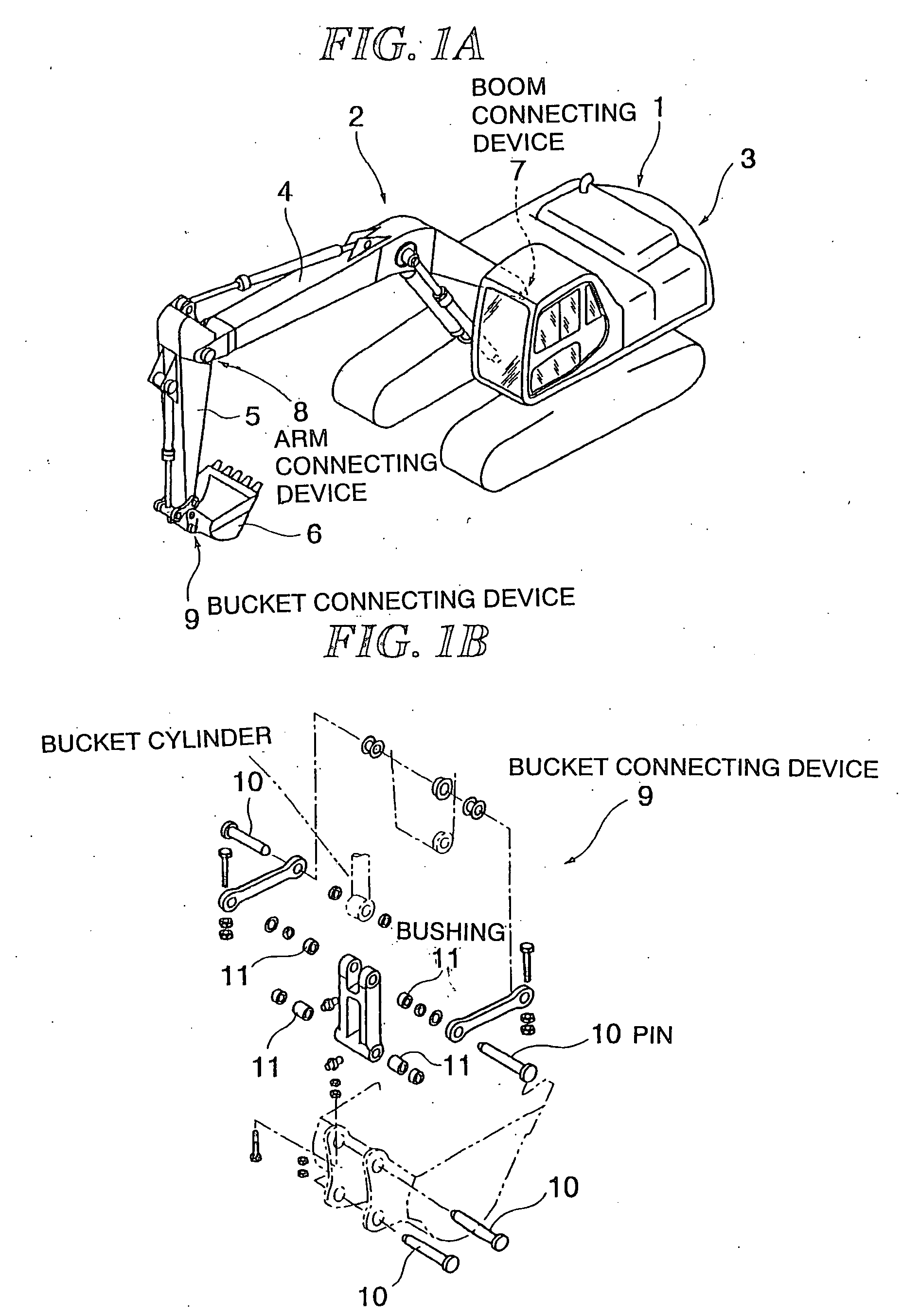
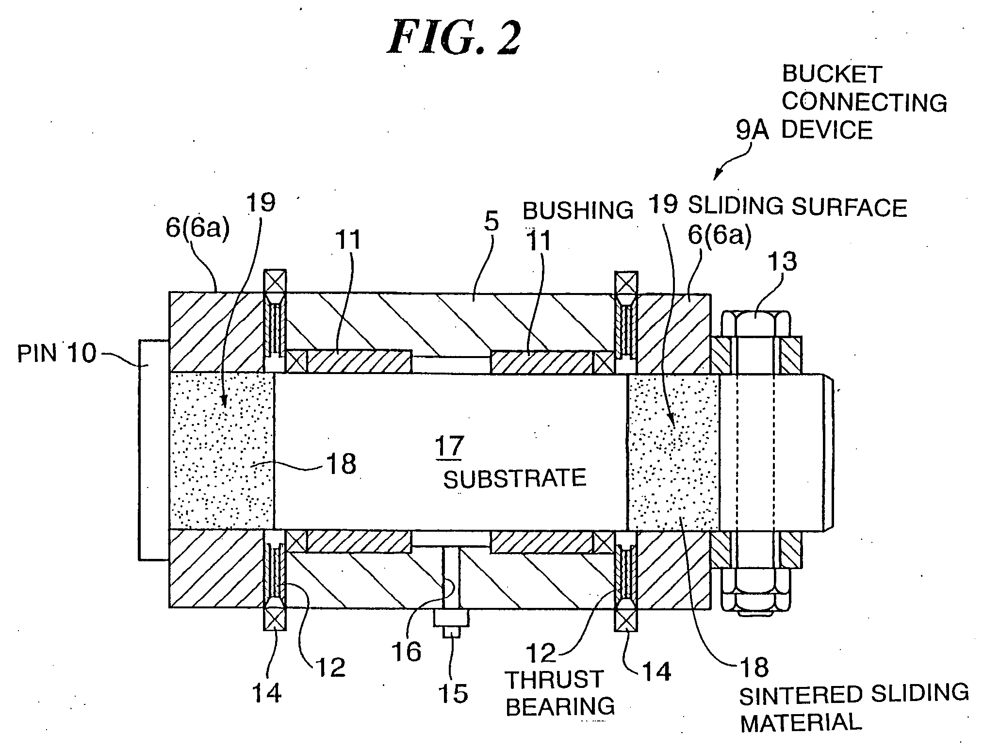
[0085]FIG. 1A is a perspective view showing a hydraulic shovel according to the first embodiment of the present invention and FIG. 1B is an exploded perspective view showing a bucket connecting device of the hydraulic shovel. FIG. 2 is a cross sectional view schematically showing a structure of the bucket connecting device according to the first embodiment of the present invention. FIG. 3A is a cross sectional view showing a structure of a bushing and FIG. 3B is a cross sectional view showing a structure of a thrust bearing.

[0086] As shown in FIG. 1A, an operating portion 2 of a hydraulic shovel 1, according to this embodiment, is provided with an upper turning body 3 to which a boom 4 is connected by a boom connecting device 7. The boom 4 is connected to an arm 5 by an arm connecting device 8, and the arm 5 is connected to a bucket 6 by a bucket connecting device 9. These connecting devices 7, 8 and 9 have the same fundamental structure. For example, the bucket connecting device 9...

embodiment 2

[0106]FIG. 4 is a cross sectional view schematically showing a structure of a bucket connecting device according to the second embodiment of the present invention. The bucket connecting device 9B has the same basic structure as that of the first embodiment except for structures of a connecting pin and a bushing. Hereinafter, only the specific structures in this embodiment will be explained, and the parts common to the first embodiment are represented with the same number as the first embodiment and description thereof is omitted.

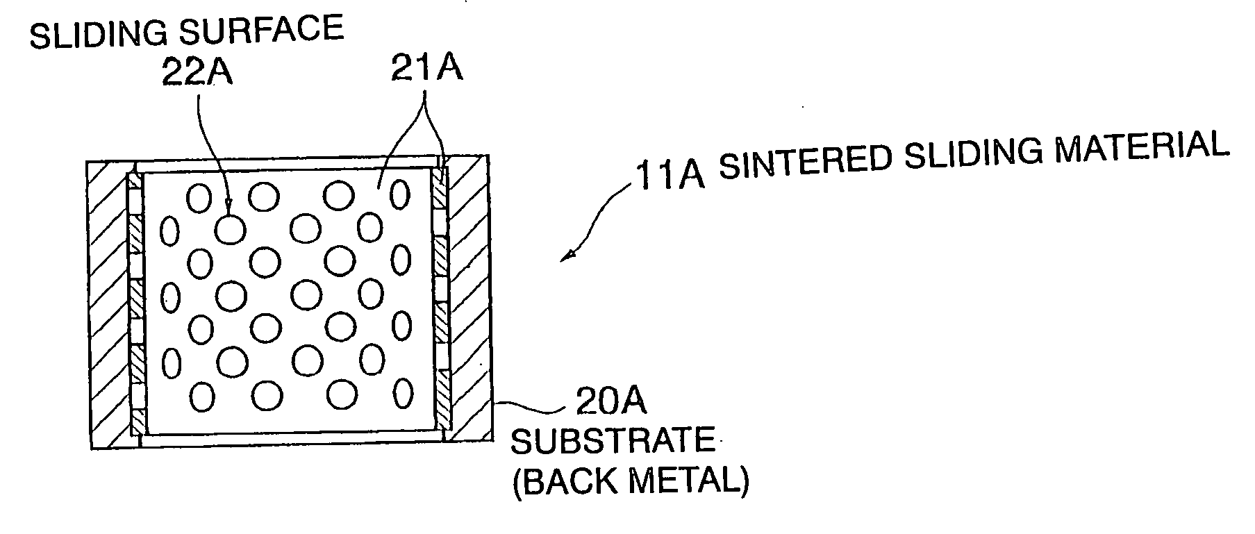
[0107] A connecting pin 26, in this embodiment, is provided with a steel substrate (a back metal) 27 functioning as an axis and sliding surfaces 29 which is made of a sintered sliding material 28, according to the present invention, combined with the substrate 27. In the connecting pin 26, the sliding surfaces 29 are formed at portions where the connecting pin 26 is sliding-contacted with the brackets 6a and the bushings 30.

[0108] The bushing 30 is compose...

example 1

[0194] Next, the preferred examples of the present invention will be described in detail with reference to accompanying drawings.

(Producing Method of Sintered Sliding Material)

[0195] In this example, using Mo(1) powder (an average grain size of 0.8 μm), Mo(2) powder (an average grain size of 4.2 μm), NiO (an average grain size of 0.7 μm), atomized Cu powder (manufactured by Nippon Atomized Metal Powder Corporation, SFR—Cu, an average grain size of 0.8 μm), Ni powder (an average grain size of 0.8 μm), TiH powder under #350 mesh and Sn powder under #350 mesh, various types mixed powder shown in table 1 were prepared. And, each mixed powder was blended with paraffin wax of 3 wt % with respect to the mixed powder and then formed with a pressure of 2 ton / cm2 into a cylindrical-shaped compact with an inner diameter of 46 mm and a height of 50 mm. Then, each compact thus obtained was sintered at 950 to 1250° C. for 1 hour and then cooled with N2 gas.

TABLE 1CONPOSITIONS(wt %)0.8μm4.7 μ...


PUM

PropertyMeasurementUnit
Grain sizeaaaaaaaaaa

Abstract

A sintered sliding material, a sliding member and a connecting device capable of demonstrating excellent seizing resistance and abrasion resistance under very bad lubricating conditions such as a high-bearing stress and slow-speed sliding condition and an oscillating condition can be provided. The sintered sliding material is composed of a sintered compact containing Cu or Cu alloy in an amount of 10 to 95 wt % and a residue made of Mo principally, in which the sintered compact has a relative density of 80% or more.

Description

FIELD OF THE INVENTION [0001] The present invention relates to a sintered sliding material, a sliding member, a connecting device and a device using the sliding member improved in seizing resistance and abrasion resistance for the purpose of withstanding severe sliding conditions such as a high-speed and high-temperature condition, a high-bearing stress and low-speed condition, and a high-bearing stress and high-speed condition. BACKGROUND OF THE INVENTION [0002] Generally, as an available bearing with a long lubrication interval or without lubricating, an oil retaining bearing in which a Cu-based or a Fe-based porous sintered alloy retains a lubricating oil in its pores has been in practical use extensively. In such a case, the Cu-based or the Fe-based porous sintered alloy is suitably selected according to operating conditions including an oil lubricating state, a sliding speed, a sliding bearing stress and the like. For example, in a high-speed and light-load sliding condition, a...

Claims


Application Information

Patent Timeline
IPC IPC(8): C25D5/10B22F3/26B32B15/01G01K5/66B22F1/00F16C33/12
CPCB22F1/0003F16C33/12F16C2360/24Y10T428/12028Y10T428/1216Y10T428/12514Y10T428/12507Y10T428/12687Y10T428/12694F16C2350/26F16C17/18B22F1/09C22C1/04
Inventor TAKAYAMA, TAKEMORIOKAMURA, KAZUOOHNISHI, TETSUO
Owner KOMATSU LTD
Why Eureka
Try Eureka