Apparatus and method for high efficiency RF power amplification using drain bias adaptation

a technology drain bias, applied in the direction of high frequency amplifier, transmission, gain control, etc., can solve the problems of low average cdma or wcdma signal power, severe efficiency penalty, and loss of much of the efficiency of a conventional rf power amplifier, so as to improve the efficiency of rf power amplifier, reduce the drain voltage, and quickly boost the drain voltage

Inactive Publication Date: 2007-01-11
SAMSUNG ELECTRONICS CO LTD
View PDF6 Cites 13 Cited by
  • Summary
  • Abstract
  • Description
  • Claims
  • Application Information

AI Technical Summary

Benefits of technology

[0017] The invention described herein seeks to improve RF power amplifier efficiency by decreasing the drain voltage during times of low signal power (>99% of the time) and quickly boosting the drain voltage during peaks in the signal (<1% of the time).
[0025] According to a yet further embodiment of the present invention, the switch timing control circuit is further capable of generating a third switch control signal that opens the second switch and a fourth switch control signal that closes the first switch after the second switch is opened by the third switch control signal.

Problems solved by technology

Unfortunately, much of the efficiency of a conventional RF power amplifier is lost due to the set drain voltage, which is constant regardless of signal level.
This results in a severe efficiency penalty when processing signals with low average power and large peak-to-average power variation, such as CDMA, WCDMA or OFDMA signals.
For example, in normal operation (e.g., >99% of the time), the average CDMA or WCDMA signal power is low and the RF transmitter exhibits very low efficiency due to the high drain voltage of the RF power amplifier.
Unfortunately, this only occurs for a small fraction of the time.
This means the drain bias voltage is set at an unnecessarily high level for most (>99%) of the signal envelope period, so that overall drain efficiency is very low.
However, these prior art RF power amplifier schemes all suffer from one or more drawbacks.
The prior art amplifiers do not disclose a mechanism for discharging the large RF amplifier drain bypass capacitance.
However, the prior art references do not disclose a method for quickly charging and discharging the bypass capacitance back to the previous voltage level.
Gain compensation during the period of high drain voltage also is an issue.
The exact timing required to compensate the amplifier gain change has a margin of error in the low nanosecond range, which is extremely difficult to realize using analog methods.
The exact gain setting required for compensation is also difficult to meet due to the gain tolerance in AGC amplifiers.
Delay compensation of the drain modulation circuit also is a problem in the prior art RF power amplifiers.
However, practical RF delay lines are usually bulky coax cables, expensive filters, or extremely high loss integrated delay lines.

Method used


Image

  • Apparatus and method for high efficiency RF power amplification using drain bias adaptation
  • Apparatus and method for high efficiency RF power amplification using drain bias adaptation
  • Apparatus and method for high efficiency RF power amplification using drain bias adaptation

Examples


Embodiment Construction

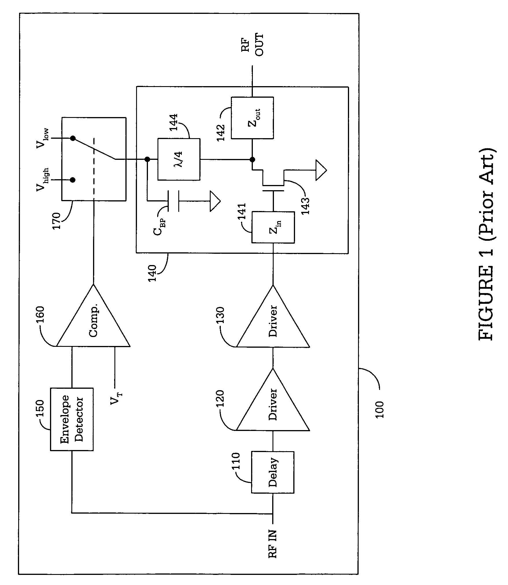
[0035]FIGS. 1 through 5 and the various embodiments used to describe the principles of the present invention in this patent document are by way of illustration only and should not be construed in any way to limit the scope of the invention. Those skilled in the art will understand that the principles of the present invention may be implemented in any suitably arranged radio frequency (RF) power amplifier.

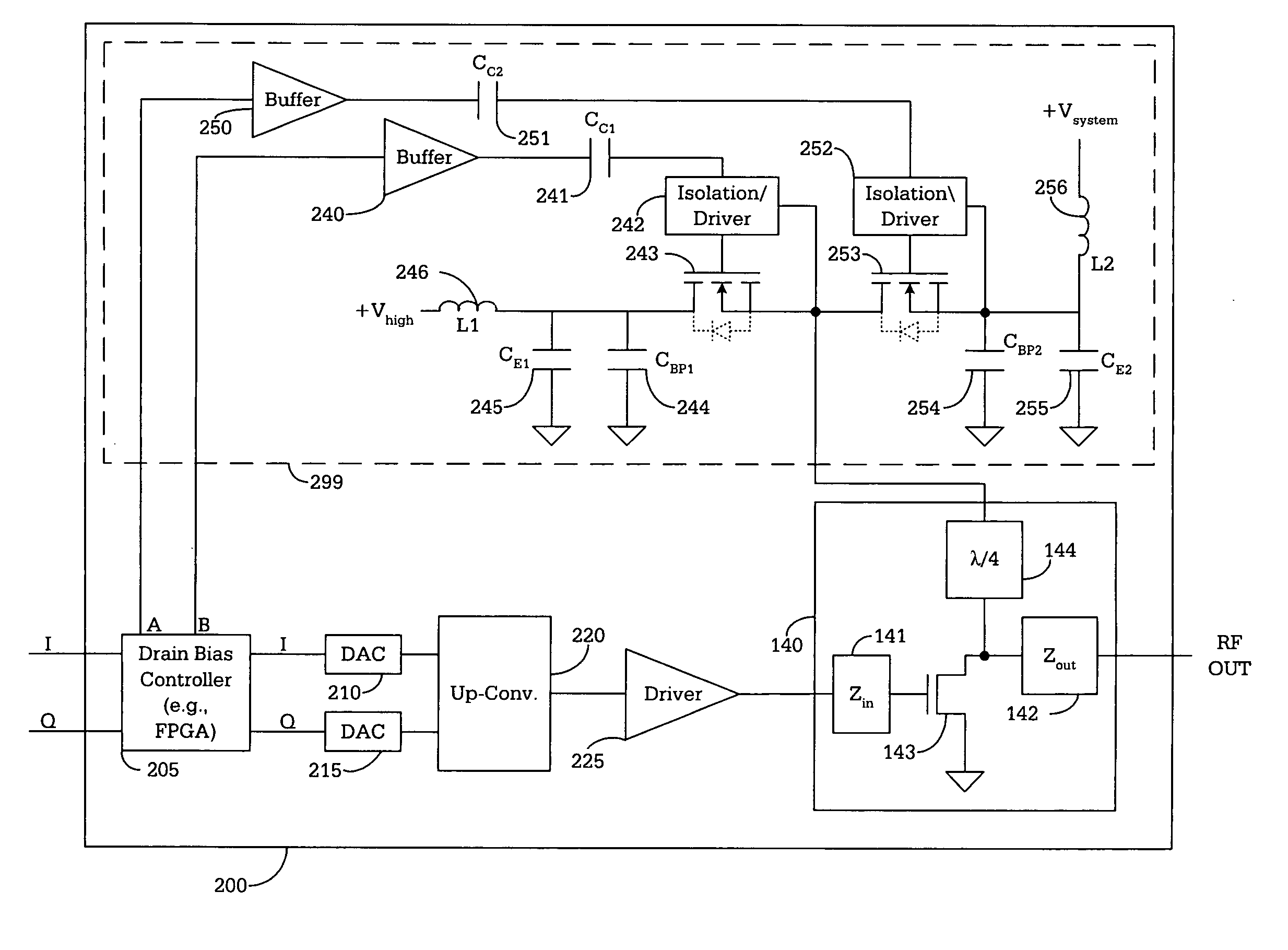
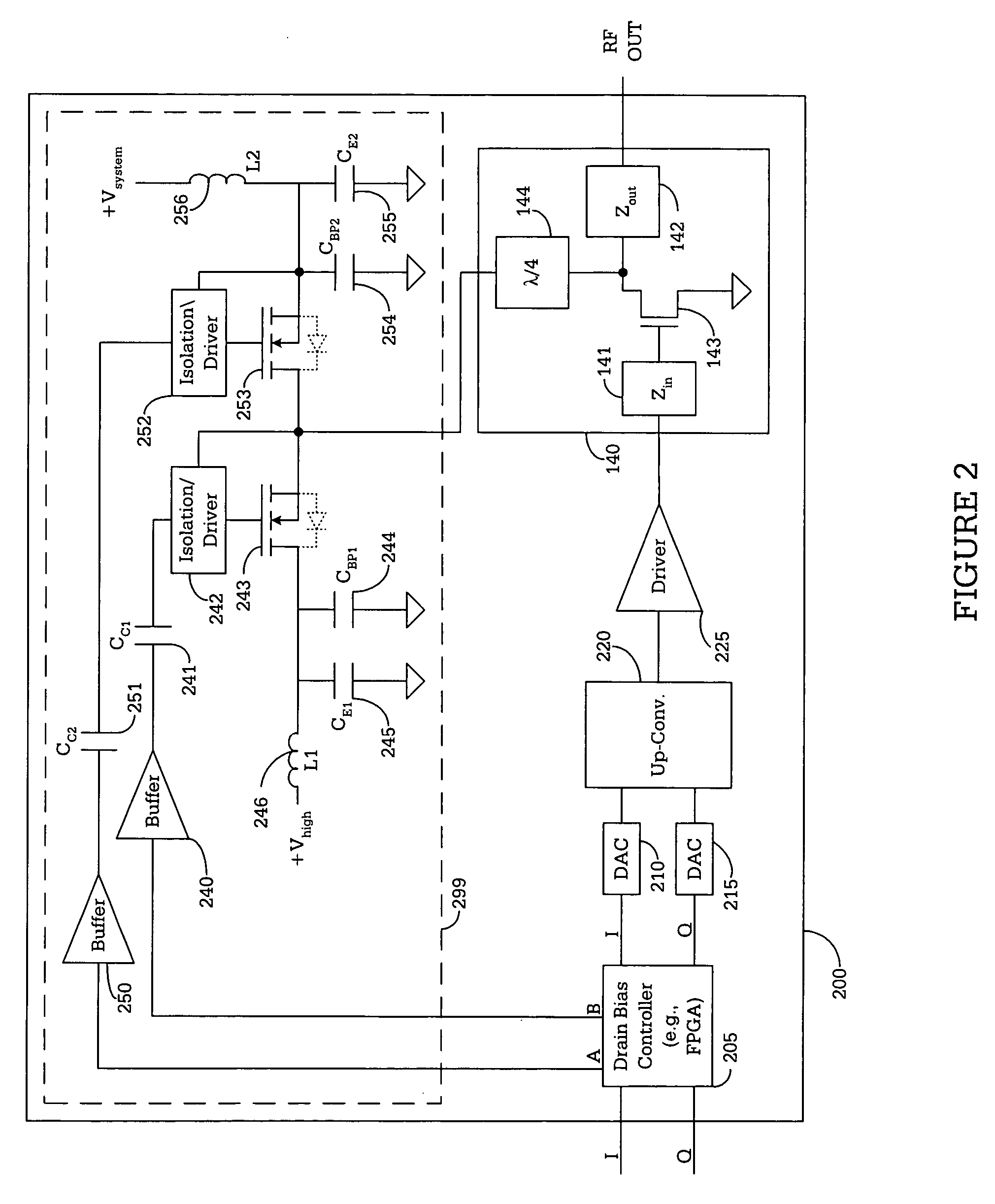
[0036]FIG. 2 is a schematic diagram illustrating one embodiment of improved RF transmitter 200, which uses drain bias adaptation (or drain supply modulation) according to the principles of the present invention. In one embodiment, RF transmitter 200 may be implemented in a base station of an OFDMA, CDMA or WCDMA wireless network. In an alternate embodiment, RF transmitter 200 may be implemented in a wireless terminal (e.g., cell phone or similar wireless device) capable of accessing an OFDMA, CDMA or WCDMA wireless network.

[0037] RF transmitter 200 comprises drain bias controller ...


PUM


Abstract

An RF transmitter having an RF power amplifier comprising: 1) a drive transistor that receives an input RF signal and generates an output RF signal; and 2) a drain bias adaptation circuit for supplying drain current to the drive transistor. The drain bias adaptation circuit comprises: i) a first switch for coupling the drive transistor drain to a system supply voltage; ii) a second switch for coupling the drive transistor drain to a high supply voltage that is greater than the system supply voltage; iii) a first bypass capacitor coupled to the first switch for reducing noise in the drain current when the first switch is closed and the second switch is open; and iv) a second bypass capacitor coupled to the second switch for reducing noise in the drain current when the second switch is closed and the first switch is open.

Description

TECHNICAL FIELD OF THE INVENTION [0001] The present invention relates generally to radio frequency (RF) power amplifiers and, more specifically, to an apparatus for improving the efficiency of an RF power amplifier using drain bias adaptation. BACKGROUND OF THE INVENTION [0002] Power dissipation and power efficiency are important operating characteristics of the radio frequency (RF) power amplifier of any RF transmitter. The more efficient the RF power amplifier is, the less expensive the transmitter is to operate, and the cooler and more reliably it runs. Since wireless communication systems of various types have become ubiquitous in society, it is important to maximize the efficiency of RF power amplifiers. [0003] Unfortunately, much of the efficiency of a conventional RF power amplifier is lost due to the set drain voltage, which is constant regardless of signal level. It is known that for Class-AB amplifiers that drain efficiency rolls off with the square root of output power. T...

Claims


Application Information

Patent Timeline
Patent Type & Authority Applications(United States)
IPC IPC(8): H04B1/04
CPCH03F1/0244H03F1/0266H03F3/189H03F3/245H04B2001/045H03F2200/15H03F2200/27H03F2200/336H03F2200/102H03F1/02H03F3/24
Inventor MONROE, ROBERTBROBSTON, MICHAEL
Owner SAMSUNG ELECTRONICS CO LTD
Why Eureka
Try Eureka