Optical disc drive and objective lens for the same

a technology of optical disc drive and objective lens, which is applied in the field of objective lens, can solve the problems of reducing focusing performance, reducing the quantity corresponding to 40% usage efficiency of light, and deteriorating focusing performance, so as to reduce the diameter of the beam spot, prevent deterioration of focusing performance, and high light efficiency

Inactive Publication Date: 2007-01-18
HOYA CORP
View PDF17 Cites 14 Cited by
  • Summary
  • Abstract
  • Description
  • Claims
  • Application Information

AI Technical Summary

Benefits of technology

[0010] The present invention is advantageous in that it provides an objective lens capable of forming a suitable beam spot while suppressing spherical aberration for each of three types of optical discs, preventing deterioration of focusing performance even when a step structure which produces undesirable diffraction order light for a lower recording density optical disc (e.g., the CD) is formed thereon, reducing a beam spot diameter to a desired level, and keeping high efficiency of light for a relatively high recording density optical disc (e.g, the HD DVD).

Problems solved by technology

However, the optical pick-up disclosed in the publication has a drawback that the optical pick-up can achieve only 40% usage efficiency of light for recordation or reproduction of information for the CD and undesired diffraction order light (e.g., first-order diffracted light in this case) having the light quantity corresponding to 40% usage efficiency of light is undesirably generated.
By such a drawback, a waveform of a focus error signal may be deformed, thereby decreasing focusing performance.
Further, in this case a suitable beam spot diameter can not be achieved.

Method used


Image

  • Optical disc drive and objective lens for the same
  • Optical disc drive and objective lens for the same
  • Optical disc drive and objective lens for the same

Examples


first example

[0164] The objective lens 10 according to the first example is provided with the phase shift structure having steps producing a single type of optical path length difference. The phase shift structure is formed on the surface 1I of the objective lens 10. Specifications of the objective lens 10 according to the first example are shown in Table 1.

TABLE 1First laserSecond laserThird laserbeambeambeamDesign wavelength (nm)405660790Focal length f (mm)3.003.113.13NA0.650.630.50magnification0.0000.000−0.026

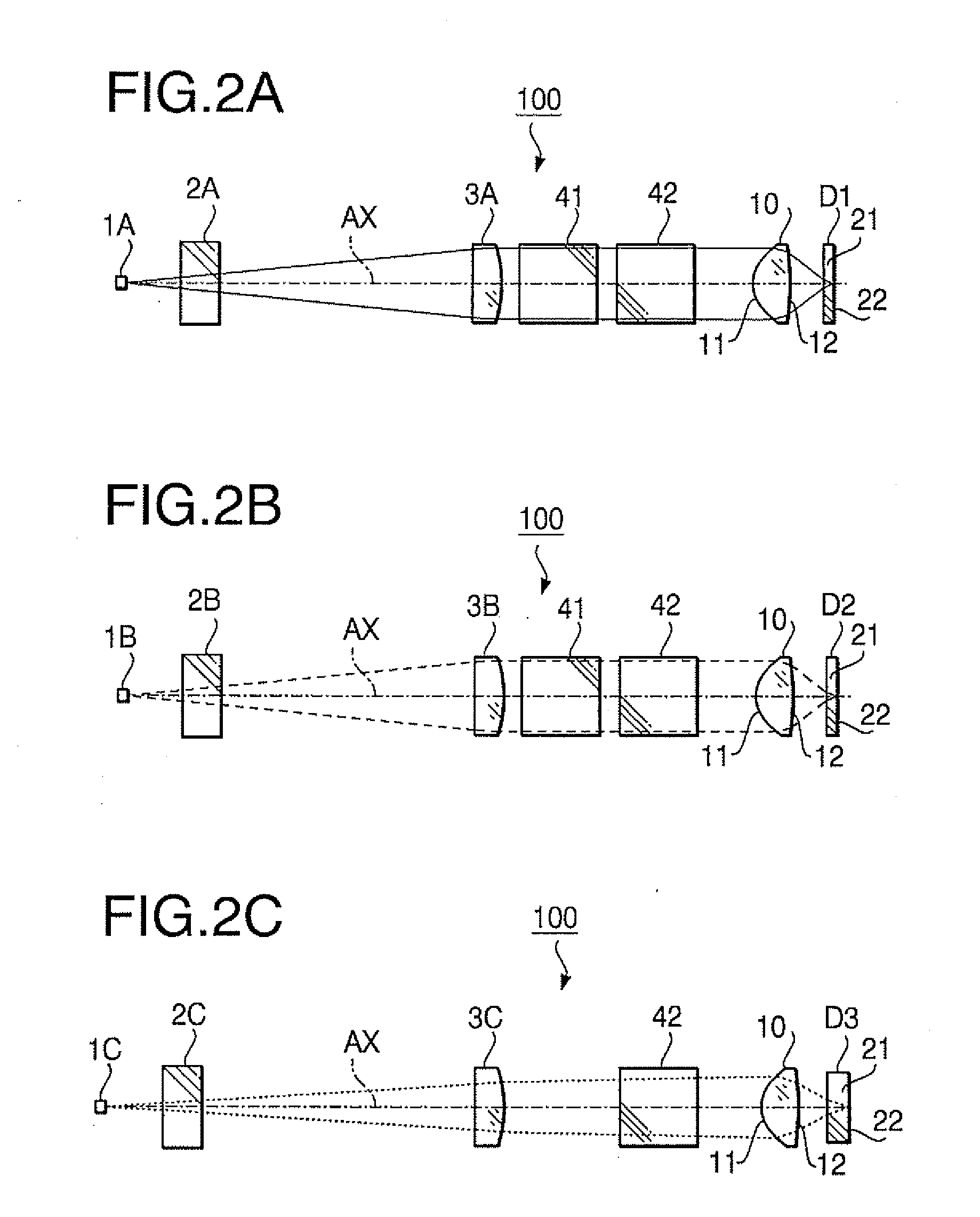
[0165] In Table 1 (and in the following similar Tables), the design wavelength is a wavelength suitable for the recording / reproducing operation of the optical disc, f represents a focal length (unit: mm) of the objective lens 10, NA represents the numerical aperture. In Table 1, the performance specifications are indicated with regard to each of the first laser beam (the optical disc D1), the second laser beam (the optical disc D2) and the third laser beam (the optical disc D3).

[0166]...

second example

[0186] The objective lens 10 according to the second example is provided with the phase shift structure having steps producing a single type of optical path length difference. The phase shift structure is formed on the surface 1I of the objective lens 10. Specifications of the objective lens 10 according to the second example are shown in Table 12.

TABLE 12First laserSecond laserThird laserbeambeambeamDesign wavelength (nm)405660790Focal length f (mm)3.003.113.13NA0.650.630.46magnification0.0000.000−0.025

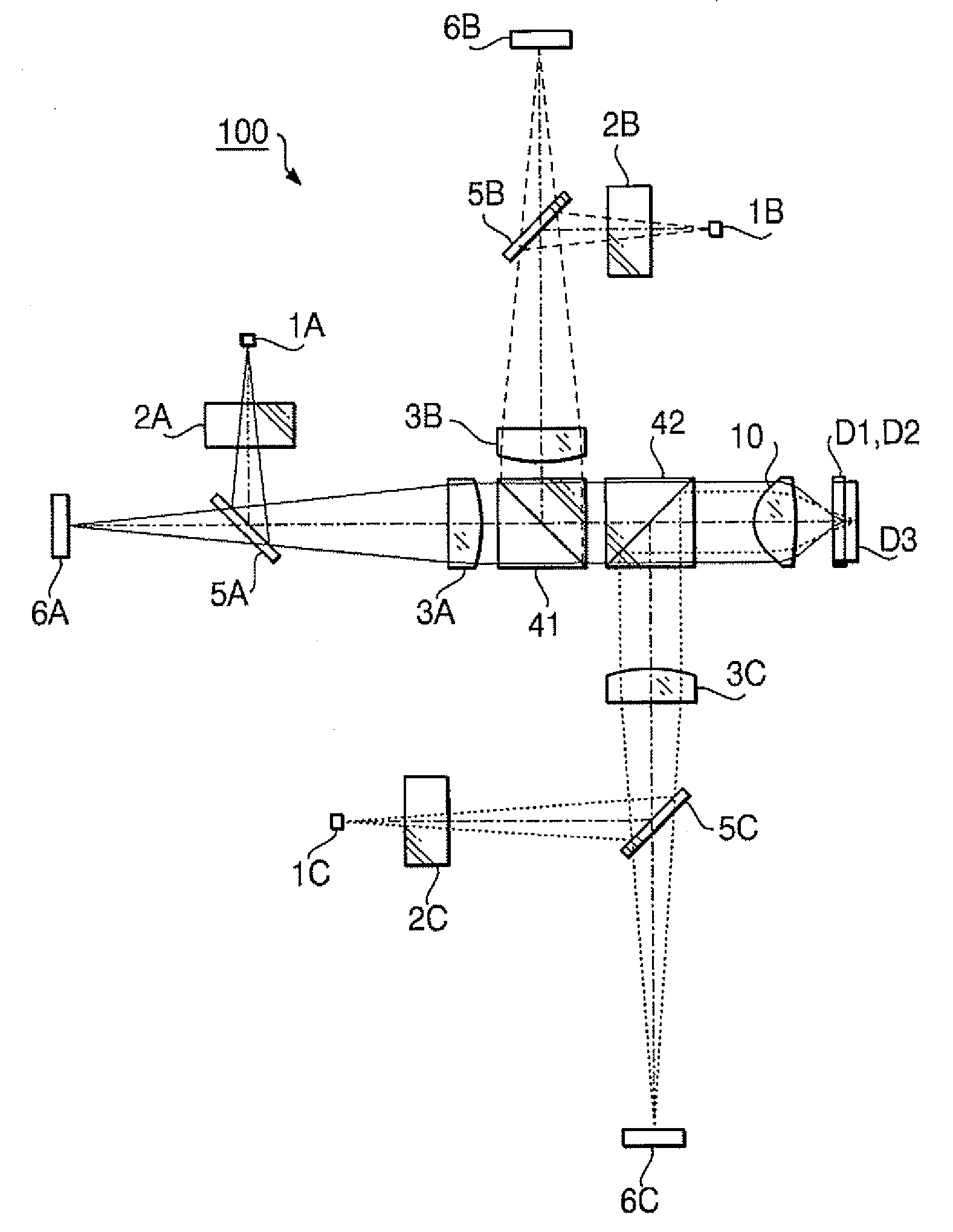
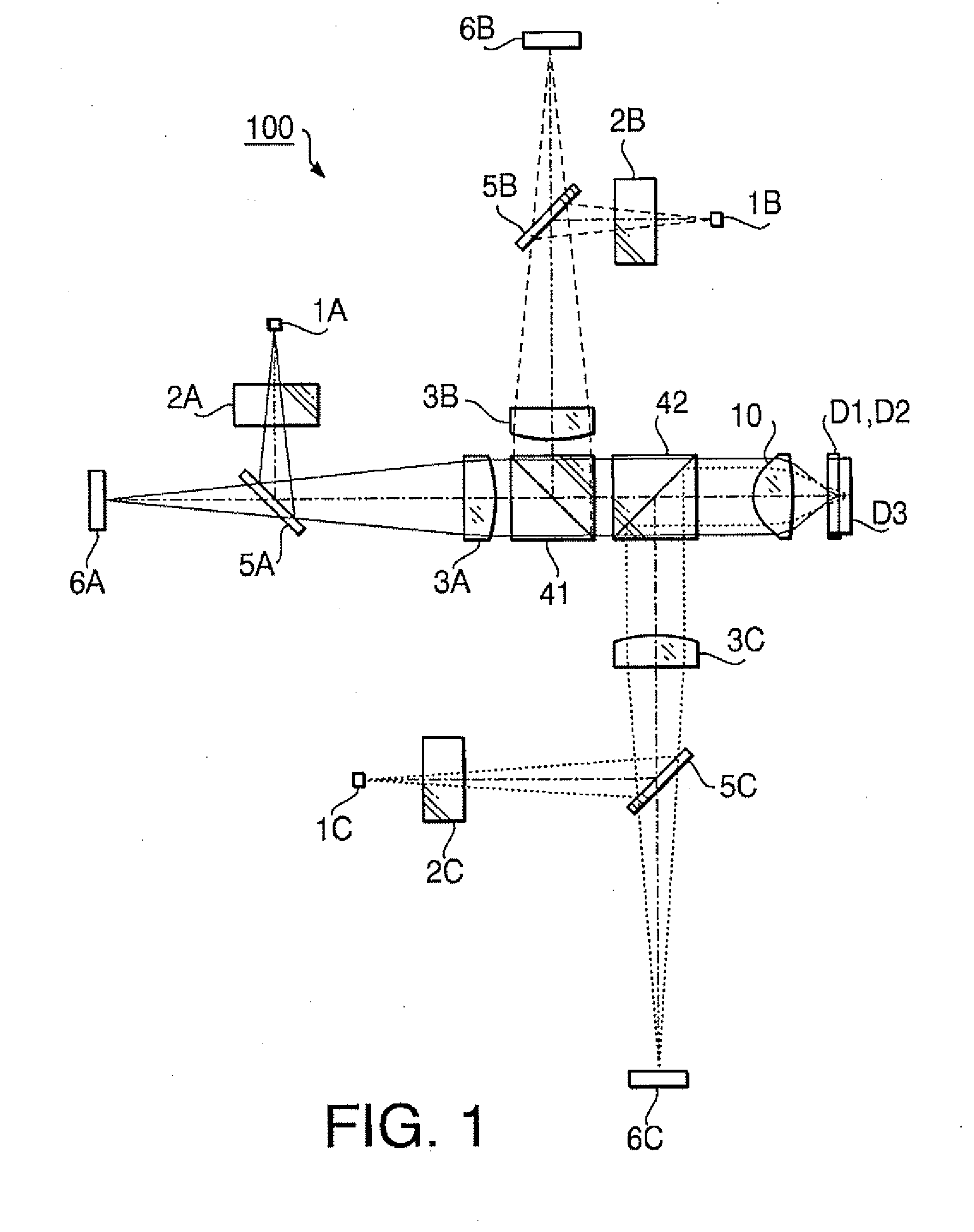
[0187] As shown by values of the magnification in Table 12, each of the first and second laser beams is incident on the objective lens 10 as a collimated beam when each of the optical discs D1 and D2 is used. When the optical disc D3 is used, the third laser beam is incident on the objective lens 10 as a diverging beam.

[0188] Table 13 shows a numerical configuration of the optical disc drive 100 when the optical disc D1 (the first laser beam) is used, Table 14 shows a numerical co...

third example

[0204] The objective lens 10 according to the third example is provided with the phase shift structure having steps producing a single type of optical path length difference. The phase shift structure is formed on the surface 11 of the objective lens 10. Specifications of the objective lens 10 according to the first example are shown in Table 23.

TABLE 23First laserbeamSecond laser beamThird laser beamDesign wavelength408660790(nm)Focal length ƒ (mm)2.252.332.35NA0.650.650.45magnification0.0000.000−0.048

[0205] As shown by values of the magnification in Table 23, each of the first and second laser beams is incident on the objective lens 10 as a collimated beam when each of the optical discs D1 and 92 is used. When the optical disc D3 is used, the third laser beam is incident on the objective lens 10 as a diverging beam.

[0206] Table 24 shows a numerical configuration of the optical disc drive 100 when the optical disc D1 (the first laser beam) is used, Table 25 shows a numerical con...


PUM

PropertyMeasurementUnit
refractive indexaaaaaaaaaa
Abbe number vdaaaaaaaaaa

Abstract

There is provided an objective lens used for three types of optical discs including by selectively using one of three types of light beams. At least one of surfaces of the objective lens is provided with a first region converging the third light beam on a recoding surface of the third optical disc. The first region has a step structure configured to have concentric refractive surface zones and to give an optical path length difference to an incident beam at each step formed between adjacent refractive surface zones. The step structure is configured such that the optical path length difference given by each step is substantially equal to an odd multiple of a wavelength of a first light beam, and a value of differentiation of an optical path difference function defining the step structure crosses zero in a height ranging from 30% to 70% of an effective diameter of the first region.

Description

BACKGROUND OF THE INVENTION [0001] The present invention relates to an objective lens employed in an optical disc drive for recording information to and / or reproducing information from a plurality of types of optical discs having different recording densities. [0002] There are various types of optical discs, such as a CD and a DVD, having different recording densities and different thicknesses of cover layers. Recently, a new technical standard optical disc, such as an HD DVD or a BD (Blue-ray Disc), having a recording density higher than that of the DVD is becoming commercially practical. Such a new technical standard optical disc has a cover layer thickness smaller than or equal to that of the DVD. Considering a usability for a user of these type of optical discs (i.e., three types of optical discs), an optical disc drive (i.e., an optical system for the optical disc drive) capable of supporting all of the three types of optical discs (i.e., to have compatibility with the three ty...

Claims


Application Information

Patent Timeline
Patent Type & Authority Applications(United States)
IPC IPC(8): G11B7/00G11B7/135
CPCG11B2007/0006G11B7/1374
Inventor KOREEDA, DAISUKEMARUYAMA, KOICHITAKEUCHI, SHUICHITASHIRO, YOSHIYUKI
Owner HOYA CORP
Why Eureka
Try Eureka