Valve port and method for vascular access

a valve port and vascular access technology, applied in the field of implantable ports, can solve the problems of significant fluid loss, and achieve the effect of reducing the risk of blood loss and reducing the variability of access

Inactive Publication Date: 2007-01-18
PROVIFLO A MISSISSIPPI CORP
View PDF40 Cites 57 Cited by
  • Summary
  • Abstract
  • Description
  • Claims
  • Application Information

AI Technical Summary

Benefits of technology

[0012] The present invention provides devices and methods for percutaneously accessing a body lumen through an implanted access port. More particularly, the present invention provides methods and devices for locking open a valve assembly within an access port by the act of inserting the access tube. Insertion may involve simply advancing the access tube in the forward direction, or it may involve additional or alternative movements such as rotation. Reversal of the needle movement and / or removal of the access tube will in turn release the lock and close the valve assembly. The present invention provides a “positive” locking action and reduces any variability in access, such as a “half-opened” valve, and reduces the risk of blood loss due to valve closure during fluid transfers.
[0013] The implantable access ports for use with the present invention are preferably capable of high volume withdrawal and / or return of blood or other fluids, particularly for patients undergoing an extracorporeal blood therapy, such as hemodialysis, hemofiltration, hemodiafiltration, apheresis, or the like. The vascular access ports allow for high volumetric rates of blood or other fluid flow therethrough, typically allowing for rates above 250 ml / min, usually above 300 ml / min, preferably at least 400 ml / min, and often 500 ml / min or higher, using a single needle or other access device. Such high volumetric flow rates are quite advantageous in reducing the time required for performing the extracorporeal blood treatment, particularly for otherwise lengthy treatments which require large total volumes of treated blood, such as hemofiltration. To ensure high flow rates and minimum time requirements, it is useful to know that the valve is completely open, allowing full access to the body lumen through the conduit while the access tube is in place. Likewise, it is beneficial to know that the valve is completely closed when the access tube is removed, either by careful disengagement or by accidental pull-out, since such high flow rates will cause a significant amount of fluid to be lost if the valve is unknowingly left open.
[0016] The space-filling elements of the latch typically comprise a pair of balls, usually opposed stainless steel balls similar to small ball bearings, disposed between the passage in the base and the bore in the valve. In valve assemblies that open and close with the action of a spring-loaded plunger, the balls are spring-biased to close against one another between the passage and the bore in the valve assembly. In one embodiment, the insertion of the access tube through the passage forces the balls apart and the access tube passes into the bore of the valve assembly. As the balls move apart (outward), they also move downward into receptacles. This movement is directed by interior walls sloping outward between the passage and the bore. Such action depresses the plunger, which opens the valve. While the access tube is inserted, the balls are held against the tube and in the receptacles by the spring-loaded plunger and the angled interior walls. Not only does this lock the valve open, but the static friction of the balls against the tube may help to hold the access tube in the passage. Interior walls with an angle of 50 degrees or greater (relative to a lateral plane through the port) have been found to provide higher frictional forces for needle retention. Removal of the tube allows the balls to move out of the receptacles in an upward direction, by action of the spring-loaded plunger, and an inward motion directed by the angled interior walls so that they are again in contact in the passage. In alternative embodiments, insertion of the access tube may be coupled with a rotational movement of the access tube. Such rotational motion would force the balls apart and facilitate the movement of the balls into the receptacles, thus opening the valve. Reversal of such movement by the access tube and / or removal of the access tube subsequently closes the valve.
[0018] The tube seat will remain locked in its depressed condition until the access tube is removed from the base. By forming the tube seat from (or lining the tube seat with) a hard material, preferably a material harder than the needle or other access device which is to be used, the likelihood of damage to the valve can be greatly reduced. Moreover, the tapered tube seat design is not prone to damaging needles when they are inserted into the port. Thus, the port of the present invention is particularly suited for use with self-penetrating, sharpened needles, such as fistula needles, unlike many ports of the prior art.

Problems solved by technology

Likewise, it is beneficial to know that the valve is completely closed when the access tube is removed, either by careful disengagement or by accidental pull-out, since such high flow rates will cause a significant amount of fluid to be lost if the valve is unknowingly left open.

Method used


Image

  • Valve port and method for vascular access
  • Valve port and method for vascular access
  • Valve port and method for vascular access

Examples


Embodiment Construction

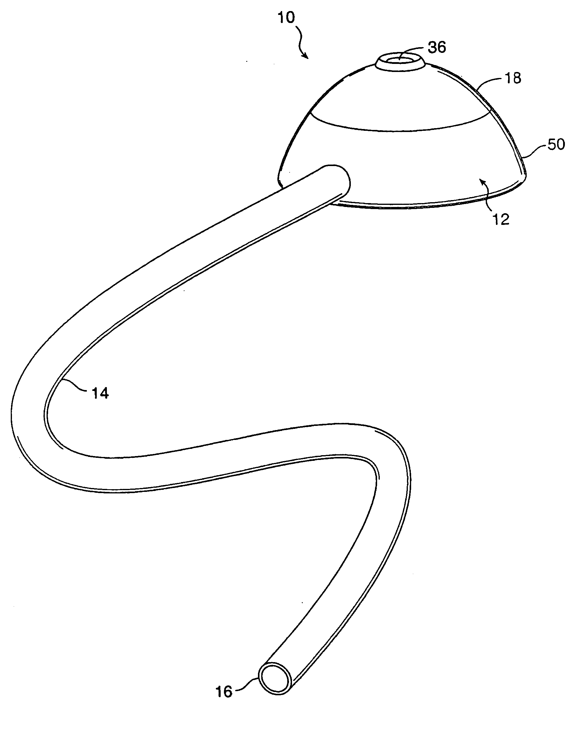
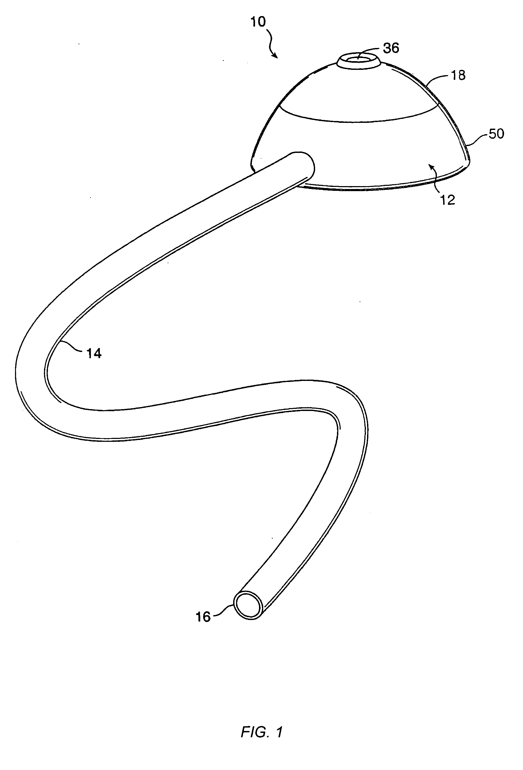
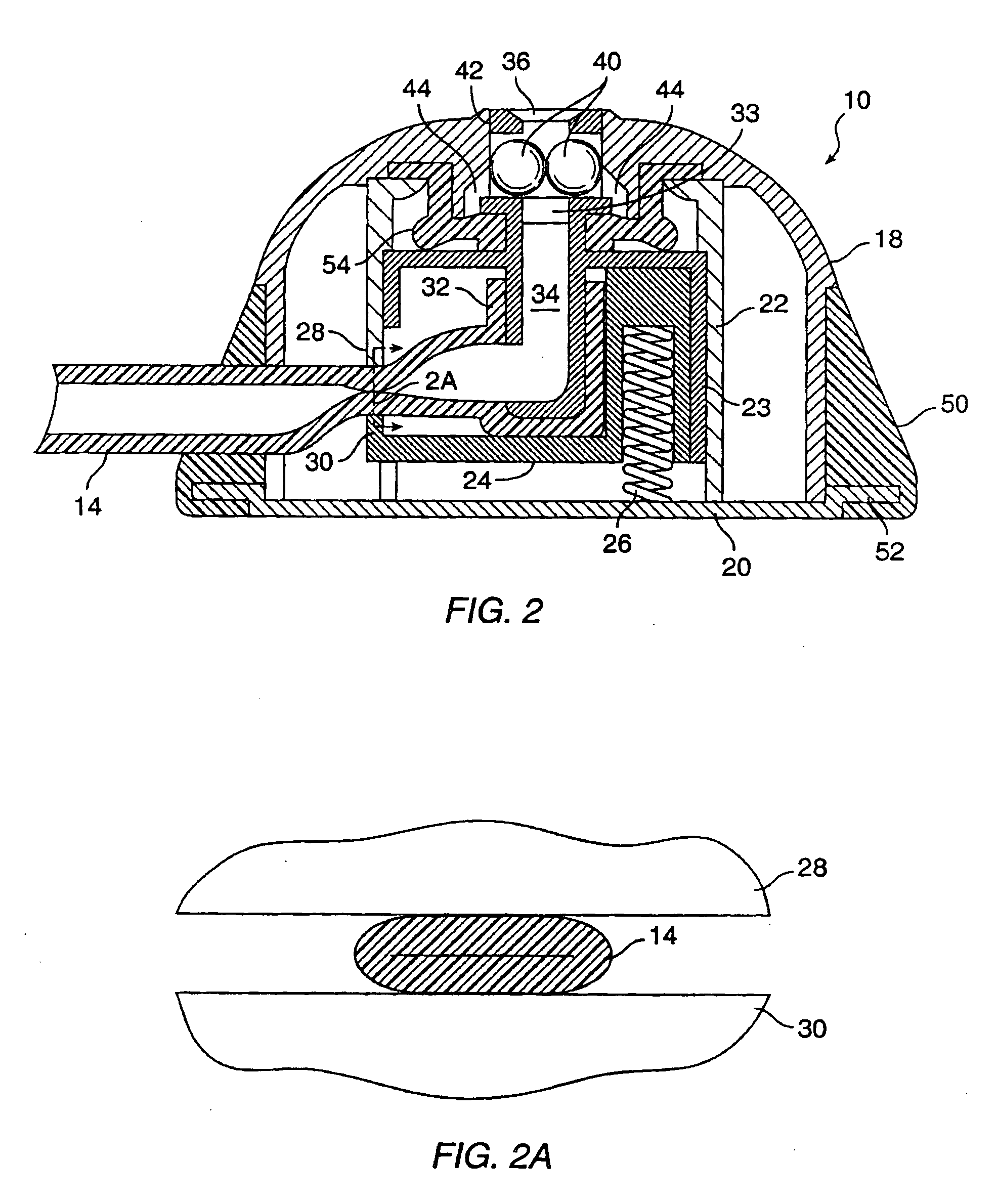
[0029] The present invention provides methods and apparatus for facilitating percutaneous access to a body lumen of a patient. Exemplary body lumens, include blood vessels, the peritoneal cavity, and the like. The methods are particularly useful for accessing blood vessels, including both arterial blood vessels and venous blood vessels. While the remaining description is directed particularly at blood vessels, it will be appreciated that the invention applies to all body lumens and cavities where selective percutaneous access might be desired. For example, the ports can be used for introduction and removal of dialysate in peritoneal dialysis procedures. Access ports according to the present invention are implanted subcutaneously so that a passage therein lies a short distance beneath the surface of the patient's skin, typically being within 3 mm to 20 mm of the skin's surface. An access tube may then be percutaneously inserted into the passage in the access port in order to provide ...


PUM


Abstract

Valved ports for accessing blood vessels and other body lumens include a lock mechanism which locks the valve fully open when a needle or other access tube is placed into the port. The lock mechanism includes a latch typically comprising one or more laterally deflectable elements, such as a pair of opposed balls. The deflected elements are pushed outwardly by the needle to engage a recess in the port which locks the valve open until the needle is removed.

Description

CROSS-REFERENCES TO RELATED APPLICATIONS [0001] The present application is a divisional of and claims the benefit of priority from application Ser. No. 09 / 431,008, filed Nov. 1, 1999, which is a continuation-in-part of application Ser. No. 08 / 942,990, filed Oct. 2, 1997 (now U.S. Pat. No. 6,007,516, issued Dec. 28, 1999), which claimed the benefit of provisional Application No. 60 / 036,124, filed on Jan. 21, 1997, the full disclosures of which are incorporated herein by reference.BACKGROUND OF THE INVENTION [0002] 1. Field of the Invention [0003] The present invention relates generally to the design and use of medical devices, and more particularly to the design and use of an implantable port for establishing temporary access to a patient's vascular system for hemodialysis and other extracorporeal blood treatments. [0004] Access to a patient's vascular system can be established by a variety of temporary and permanently implanted devices. Most simply, temporary access can be provided ...

Claims


Application Information

Patent Timeline
Patent Type & Authority Applications(United States)
IPC IPC(8): A61M31/00
CPCA61M39/0208A61M2039/009A61M39/26A61M39/0693
Inventor BURBANK, JEFFREY H.BRUGGER, JAMES M.
Owner PROVIFLO A MISSISSIPPI CORP
Why Eureka
Try Eureka