
Full spectral range spectrometer

a spectrometer and full spectral range technology, applied in the field of monochromators, to achieve the effects of increasing system complexity, high precision spectral analysis, and prolonging spectral acquisition tim

Inactive Publication Date: 2007-01-25
CHEN LIANGYAO +2
View PDF2 Cites 39 Cited by
  • Summary
  • Abstract
  • Description
  • Claims
  • Application Information

AI Technical Summary

Benefits of technology

[0022] In the present invention, we made significant improvements on the design of a monochromator. An array of several gratings combined with an advanced CCD detector array is used, arranged in a manner to enable coverage of the entire desired wavelength analysis without requiring any mechanical moving parts. For example, if the desired wavelength coverage is the entire 200-1100 nm range, depending on the accuracy requirements, we can use an array of three or more gratings with each being set at a predetermined angle to simultaneously cover a sub-section of the full wavelength range of the spectrum As a result, the full desired spectral range can be realized in one instant (one CCD integration time) in the present invention. Furthermore, the design and construction of the new monochromator system, without any moving parts and related controlling devices, is much simpler. In addition, the new design makes the system more reliable and much faster in obtaining the desired spectra, with longer instrument life with minimum required maintenance and service needs. Theory and Operation of the Invention
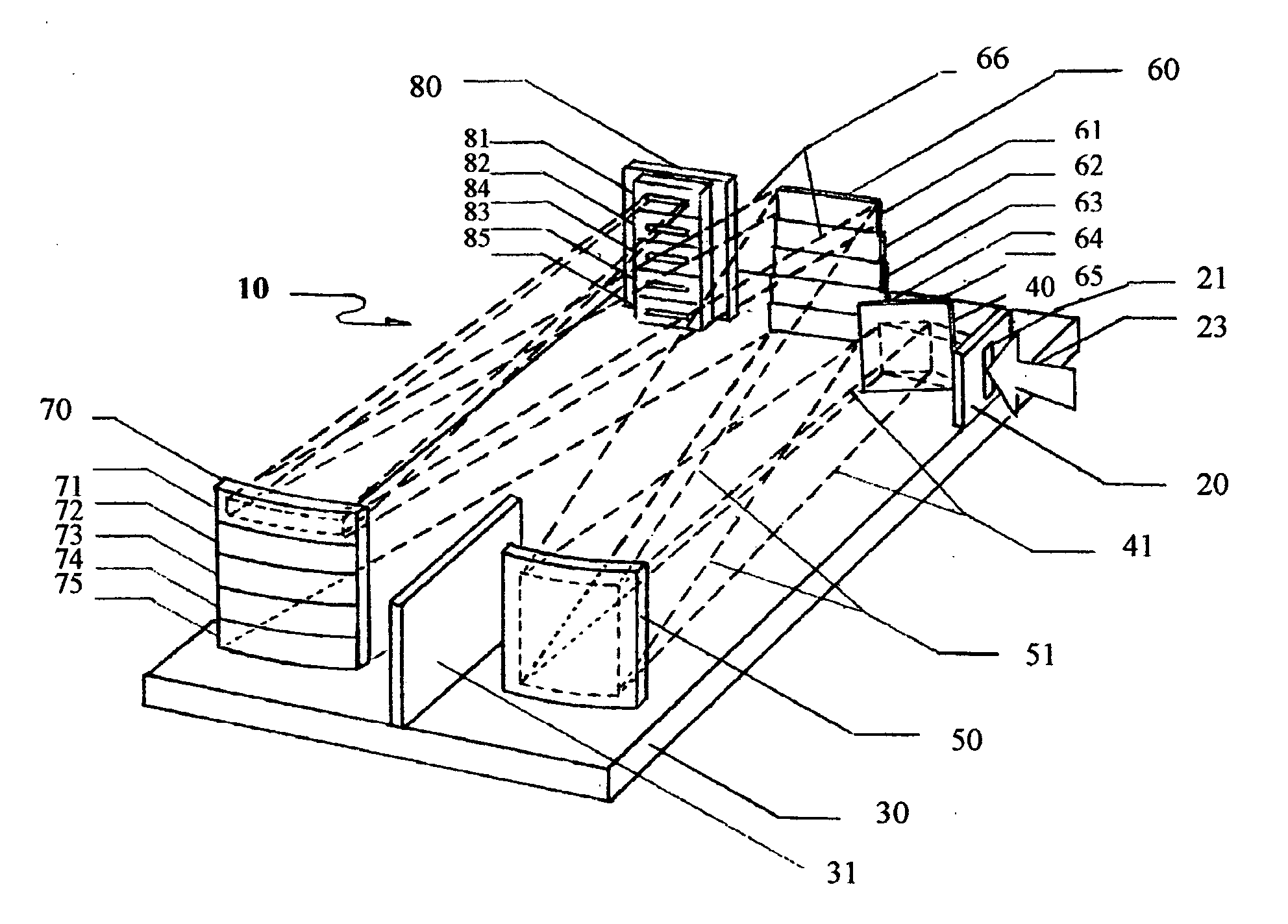
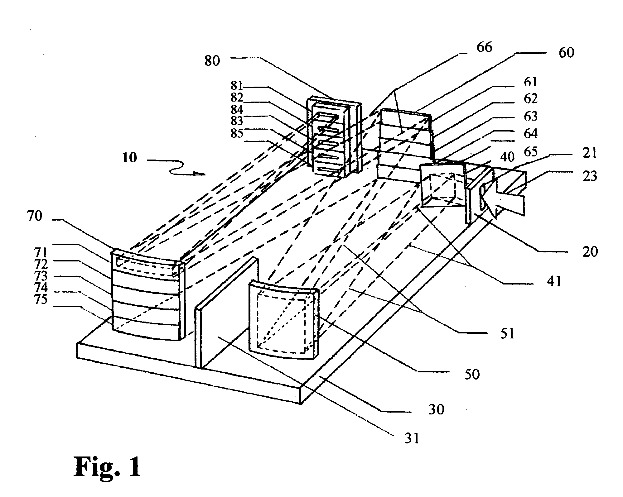
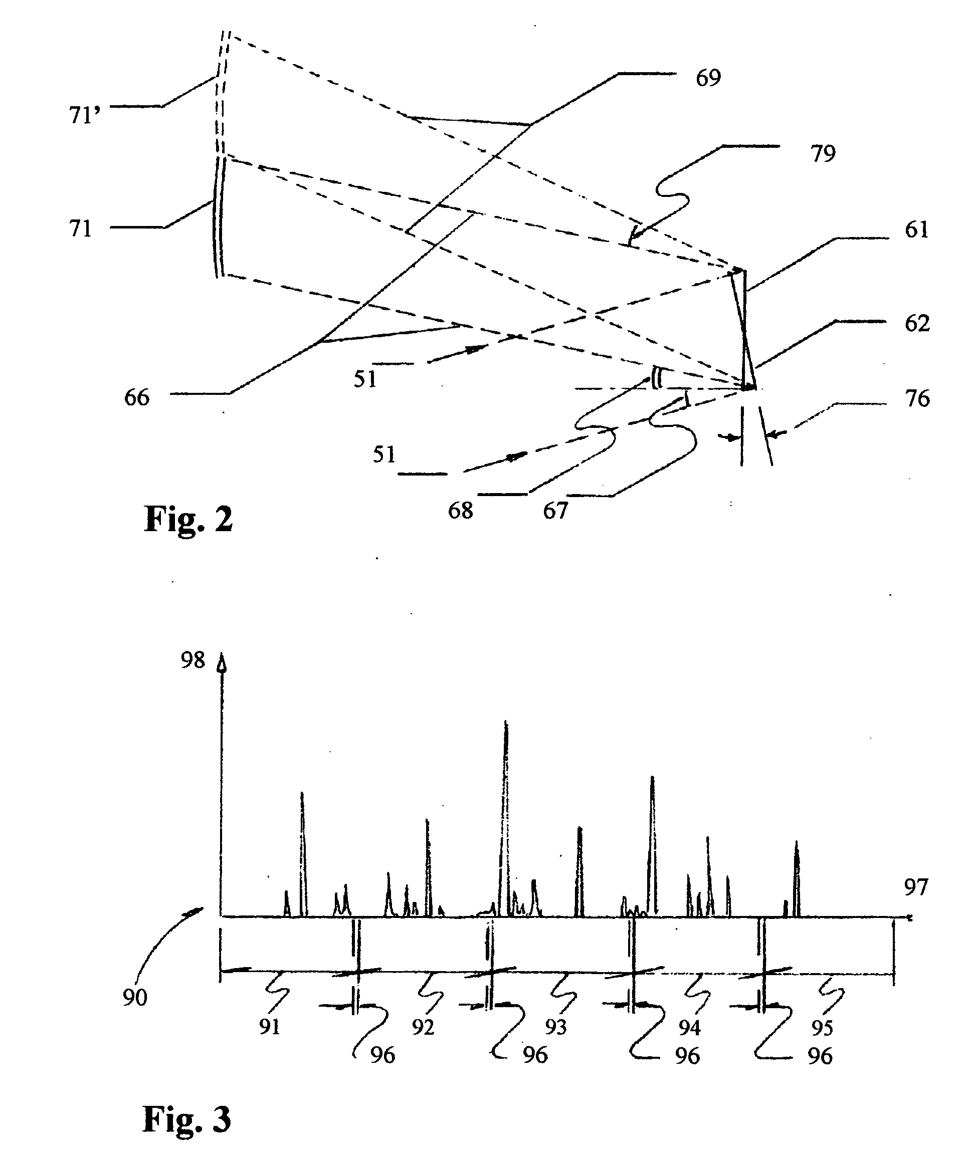
[0027] The present invention adopts an entirely different approach. The principal elements involved in this innovation include: (1) to send the incident radiation spectrum to several fixed gratings of the same or different groove spacing, one above another; (2) to image the spectrum from each grating simultaneously on a separate horizontal section of a position-sensitive detector, e.g., a charge-coupled detector (CCD; and (3) to seamlessly splice together the spectrum from each horizontal section of the detector into the full desired spectrum using digital means. The new device employs no moving parts and requires no in-situ adjustment of grating angles or interchanging of gratings, and thus eliminates the said shortcomings accompanying the conventional designs.
[0028] In actual design, depending on operational requirements, it is possible to offset the angle of the plane grating to vary the angle of incidence α in Equation (2) or use different grating ruling densities, or use a combination of both. When the latter is adopted, broad wavelength coverage with high precision spectral analysis can be achieved without resulting in either increasing system complexity or lengthening spectral acquisition time.
[0029] The detector is an array of photosensitive elements (“pixels”), usually N×N. In ideal use, a small section of the spectrum Δλ lands on a vertical stripe of the detector, one pixel wide and N pixels high. For highest resolution, radiation in the range Δλ determined by the entrance slit width, the grating width, and the quality and alignment of the grating and mirrors will just fill one-pixel width. The signal from Δλ will be proportional to N. For a given incident photon flux, the signal-to-noise ratio from an ideal detector will be proportional to √N. In the present invention, the spectrum from one of the g gratings, will occupy N / g pixels in a vertical stripe. The ideal signal-to-noise ratio becomes √N / √g, smaller by a factor of 1 / √g. g typically will be 2-5. The loss in signal to noise will not be excessive.

Problems solved by technology

To make a monochromator with a signal detector of sufficient width that it is capable of covering the broad range of, β angles to record the full desired range of spectral analysis effectively and efficiently, has been proven difficult, often resulting, in the existing practice, to the use of manually or mechanically rotating the grating or changing gratings.

Method used


Image

  • Full spectral range spectrometer
  • Full spectral range spectrometer
  • Full spectral range spectrometer

Examples


Embodiment Construction

[0033]FIGS. 1 through 3 show the principal elements of this invention. Numeral 10 in FIG. 1 designates the monochromator designed to embody the fundamental theory and operational principles employed in this invention FIG. 2 illustrates the concept of selecting the preset angle of the grating plane to bring the offset of the full spectrum from the sub-set diffracted spectra

[0034] With reference to FIG. 1, a plate 20 with an adjustable width vertical slit 21 is mounted on the base plate 30 to allow incident optical radiation 23 to enter the monochromator and to properly position it on the reflection mirror 40. The reflected radiation 41 is directed onto a concave mirror 50 to produce optically collimated plane waves 51. A partition plate 31 is properly placed adjacent to the concave mirror 50.

[0035] As illustrated herein FIG. 1, when the collimated waves reach the array of gratings 60, they are horizontally sliced into a number of spectral subsections. The number of subsections can ...


PUM


Abstract

A spectrometer is designed capable of effectively covering the full desired spectral range using an array of multiple diffraction gratings arranged in gradually differentiated angles to diffract certain sub-range of photon wavelengths to the target detectors without relying on mechanically changing gratings or use of any moving parts. The optically subdivided spectral analysis results are then electronically integrated to accurately yield the desired full range spectral measurement at a speed compatible to the limit of optical and digital analyzers' speed of the measuring system without manual adjustment and / or mechanical movement delays.

Description

FIELD OF INVENTION [0001] The present invention relates to a monochromator used as an optical spectrum analyzer, which employs several diffraction gratings, along with possible collimating and beam-deflection mirrors, and with a position-sensitive detector to enable coverage of the entire desired spectral range without requiring any motion mechanism to cause continuous or intermittent scanning action. BACKGROUND OF THE INVENTION [0002] A spectrometer is a basic instrument used to spectrally disperse light in the infrared (IR—wavelengths longer than 750 nm), visible (wavelength between 400 to 750 nm), and ultraviolet (UV—wavelengths shorter than 400 nm) spectral regions and to record the spectrum, photon flux or radiation intensity, as a function of wavelength to allow for clear identification of the source and characteristics of the incident radiation. The spectrometer has wide and important applications in the optical, electro-optical, magneto-optical, and astrophysical research fi...

Claims


Application Information

Patent Timeline
IPC IPC(8): G01J3/28
CPCG01J3/02G01J3/0262G01J3/36G01J3/1804G01J3/0294
Inventor CHEN, LIANGYAOLYNCH, DAVID W.KAO, DAVID T.
Owner CHEN LIANGYAO
Learn More