
Methods and systems for cardiac valve delivery

a technology for heart valves and delivery methods, applied in the field of cardiovascular surgery, can solve the problems of long and tedious open-heart valve repair or replacement surgery, prolonged hospitalization and painful recovery period for patients, and significant trauma

Active Publication Date: 2007-02-01
MEDTRONIC 3F THERAPEUTICS
View PDF48 Cites 483 Cited by
  • Summary
  • Abstract
  • Description
  • Claims
  • Application Information

AI Technical Summary

Benefits of technology

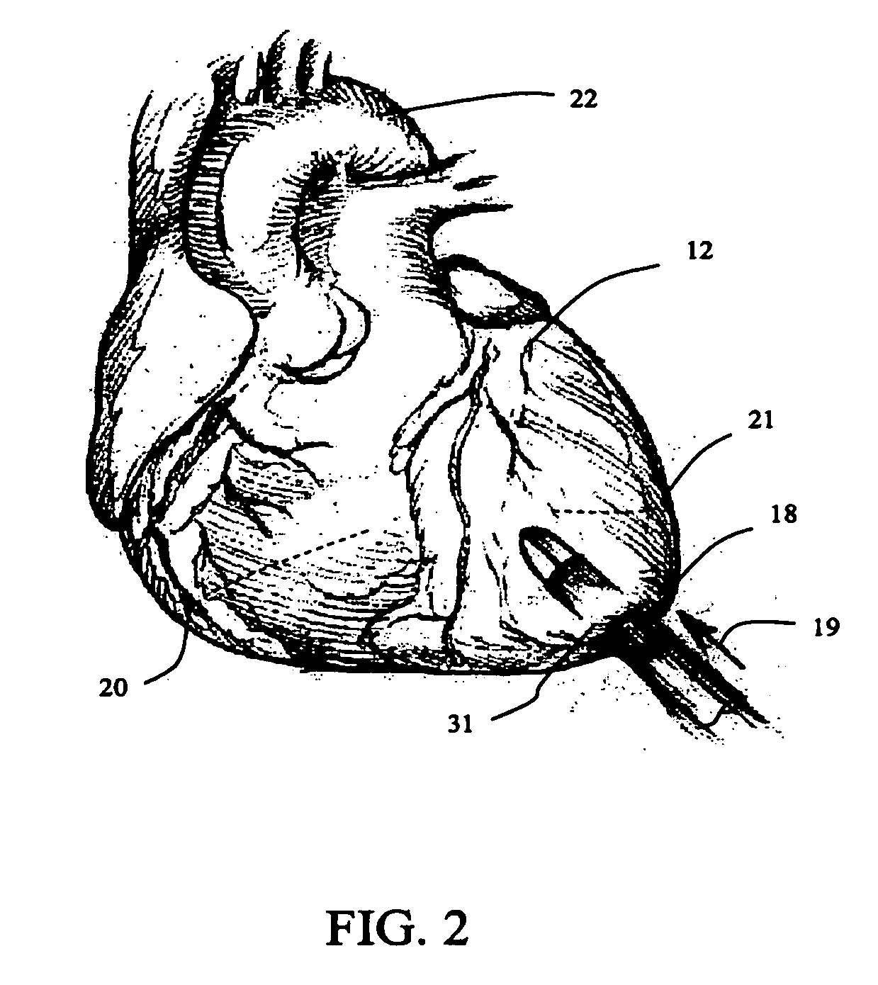
[0016] The unique anatomical structure of the apical area permits the introduction of various surgical devices and tools into the heart without significant disruption of the natural mechanical and electrical heart function. Because the methods and systems of the present invention permit direct access to the heart and great vessels through the apex, they are not limited by the size constraints which are presented by minimally invasive percutaneous valve surgeries. While access to the heart through peripheral (e.g. femoral, jugular, etc) vessels in percutaneous methods are limited to the diameter of the vessel (approximately 1 to 8 mm), access to the heart through the apical area is significantly larger (approximately 1 to 25 mm or more). Thus, apical access to the heart permits greater flexibility with respect to the types of devices and surgical methods that may be performed in the heart and great vessels.
[0020] The delivery system may be used to deliver a variety of prosthetic heart valves, including stented and stentless tissue valves. In one embodiment of the present invention, the delivery member comprises a mechanical or inflatable expanding member to facilitate implantation of the prosthetic valve at the target site. In another embodiment of the present invention, the delivery member is a balloon. In another embodiment of the present invention, the delivery member is a device used to expand folded valves. In yet another embodiment of the present invention, the delivery member may comprise an inflatable balloon member, whose distal and proximal ends have substantially larger cross-sectional areas than the portion of the balloon covered by the prosthesis, to prevent prosthesis migration. In a further embodiment of the present invention, the delivery system may comprise a duct or perfusion tube to allow blood flow through the delivery member during the procedure.
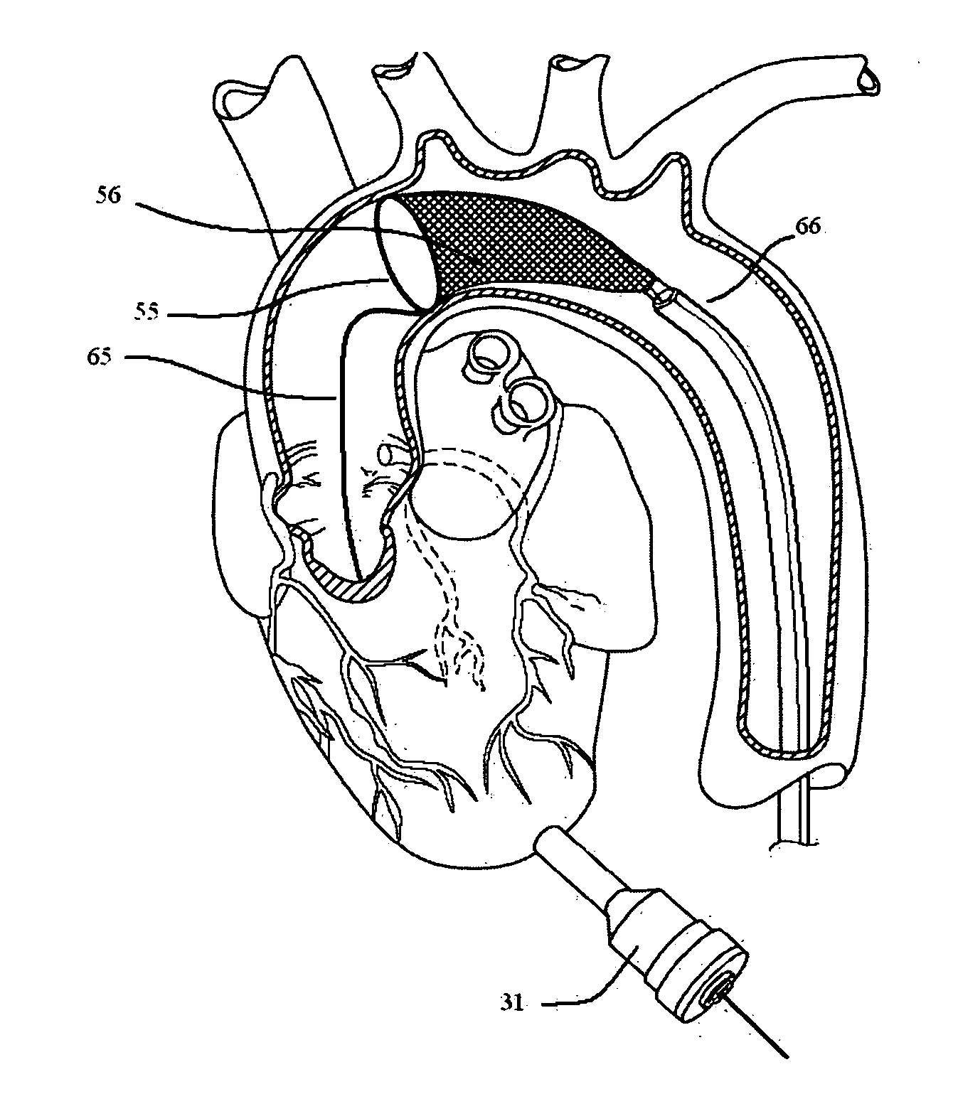
[0024] The present invention also provides for devices and methods for providing distal embolic protection and a temporary valve. In one embodiment of the present invention, the distal embolic protection system provides a filter member for trapping embolic material that concurrently functions as a temporary valve. The filter and temporary valve assembly prevents flush back of embolic material and debris, while still allowing fluid flow into the filter during surgery. The valve-filter combination may be compressed and expanded to allow entry into small blood vessels or other body cavities. In one embodiment of the present invention, the filter assembly is implanted in the heart or great vessel of the heart, downstream from the surgical site.
[0027] In another embodiment of the present invention, a positioning balloon is used to help position the Scapus™ correctly such that the new prosthesis (or alternatively other tools) land in the proper location.

Problems solved by technology

Open-heart valve repair or replacement surgery is a long and tedious procedure and involves a gross thoracotomy, usually in the form of a median sternotomy.
This method, however, is highly invasive and often results in significant trauma, risk of complications, as well as an extended hospitalization and painful recovery period for the patient.
The use of minimally invasive approaches, however, introduces new complexities to surgery.
An inherent difficulty in the minimally invasive percutaneous approach is the limited space that is available within the vasculature.
Consequently, the introduction of tools and prosthetic devices becomes a great deal more complicated as compared to open-chest surgeries.
In-vivo studies have shown that catheter-based valve delivery instrumentation may not be well adapted for trans-apical procedures.
When inserting balloon catheters, as described in U.S. Pat. No. 6,582,462 and U.S. patent application Ser. No. 10 / 831,770, it is difficult to steer the balloon and the valve into position resulting from the lack of rigidity and the inherent flexibility of catheters.
Catheters are also frequently susceptible to twisting.
Even so, it is difficult to steadily and accurately deliver tools and devices over long distances.
Accordingly, while open-heart surgery produces beneficial results for many patients, numerous others who might benefit from such surgery are unable or unwilling to undergo the trauma and risks of current techniques.

Method used


Image

  • Methods and systems for cardiac valve delivery
  • Methods and systems for cardiac valve delivery
  • Methods and systems for cardiac valve delivery

Examples


Embodiment Construction

[0049]FIGS. 1 through 16 show embodiments of the methods and systems of the present invention for the repair, removal, and / or delivery of prosthetic valves, and also for providing distal embolic protection and a temporary valve during cardiovascular procedures.

Valve Delivery Method and Implantation System

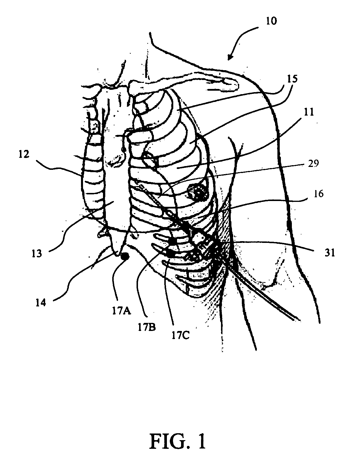
[0050]FIG. 1 is a partial front view of the chest 11 of a patient 10 and shows the position of a surgical tool 29 in relation to other anatomical landmarks, such as the sternum 13, xiphoid 14, ribs 15, and heart 12. A surgical tool 29 is depicted as entering the body cavity through the fifth intercostal space 16 and through the apex of the heart 12. The surgical tool 29 is seen inserted through an access system 31. The surgical tool 29 may contain devices or systems used for surgical procedures in or on the heart or the greater vessels of the heart. In one embodiment of the current invention, the surgical tool 29 is a delivery system. In another embodiment of the current inventio...


PUM


Abstract

The present invention provides systems and methods for the repair, removal, and / or replacement of heart valves. The methods comprise introducing a delivery system into the heart, wherein a prosthesis is disposed on the delivery member attached to the delivery system, advancing the prosthesis to the target site, and disengaging the prosthesis from the delivery member at the target site for implantation. The present invention also provides implant systems for delivering a prosthesis to a target site in or near the heart. In one embodiment of the present invention, the implant system comprises a delivery system, an access system, and a prosthesis.

Description

REFERENCE TO RELATED APPLICATIONS [0001] This application claims priority to Provisional Application Ser. No. 60 / 702,892 filed Jul. 27, 2005; Provisional Application Ser. No. 60 / 717,879 filed Sep. 16, 2005; Provisional Application Ser. No. 60 / 734,429 filed Nov. 8, 2005; Provisional Application Ser. No. 60 / 740,694 filed Nov. 29, 2005; and Provisional Application Ser. No. 60 / 762,909 filed Jan. 27, 2006; all of which are incorporated herein by referenceFIELD OF THE INVENTION [0002] The present invention relates generally to methods and systems for cardiovascular surgery. BACKGROUND OF THE INVENTION [0003] Various surgical techniques may be used to repair a diseased or damaged heart valve, such as annuloplasty (contracting the valve annulus), quadrangular resection (narrowing the valve leaflets), commissurotomy (cutting the valve commissures to separate the valve leaflets), or decalcification of valve and annulus tissue. Alternatively, the diseased heart valve may be replaced by a prost...

Claims


Application Information

Patent Timeline
Patent Type & Authority Applications(United States)
IPC IPC(8): A61F2/24A61F2/01
CPCA61F2/013A61F2/2418A61F2/2433A61F2/91A61F2230/001A61F2250/0039A61F2002/018A61F2230/0006A61F2230/0065A61F2230/0067A61F2230/0069A61F2230/008A61B2017/22098A61F2/2427
Inventor BERGHEIM, BJARNECUEVAS, WALTERDUMONTELLE, JEFFREY
Owner MEDTRONIC 3F THERAPEUTICS
Learn More