Communication transceiver architecture

a technology of communication transceiver and transceiver body, which is applied in the direction of satellite communication transmission, electrical apparatus, radio transmission, etc., can solve the problems of reducing the system's sensitivity to slight misalignment and environmental factors such as vibration and temperature changes, and achieve the effect of reducing the system's sensitivity

Active Publication Date: 2007-02-08
PERATON INC
View PDF5 Cites 114 Cited by
  • Summary
  • Abstract
  • Description
  • Claims
  • Application Information

AI Technical Summary

Benefits of technology

[0008] According to an exemplary embodiment of the present invention, a free-space communication transceiver includes: a telescope for transmitting and receiving laser beams; a data laser transmitter module for generating a transmit laser beam modulated with data; an optical receiver module for processing a receive laser beam to recover data; and a beamsplitter that directs the transmit laser beam from the data laser transmitter module to the telescope and directs the receive laser beam from the telescope to the optical receiver module. Between the beamsplitter and the telescope, the transmit and receive laser beams travel along a common optical axis as collinear, collimated free-space beams, which reduces the system's sensitivity to slight misalignments and environmental factors such as vibration and temperature changes. Preferably, the transmit and receive laser beams are randomly polarized. Eye-safe wavelengths can be use for all transmitted laser beams in the system.

Problems solved by technology

Between the beamsplitter and the telescope, the transmit and receive laser beams travel along a common optical axis as collinear, collimated free-space beams, which reduces the system's sensitivity to slight misalignments and environmental factors such as vibration and temperature changes.

Method used


Image

  • Communication transceiver architecture
  • Communication transceiver architecture
  • Communication transceiver architecture

Examples


Embodiment Construction

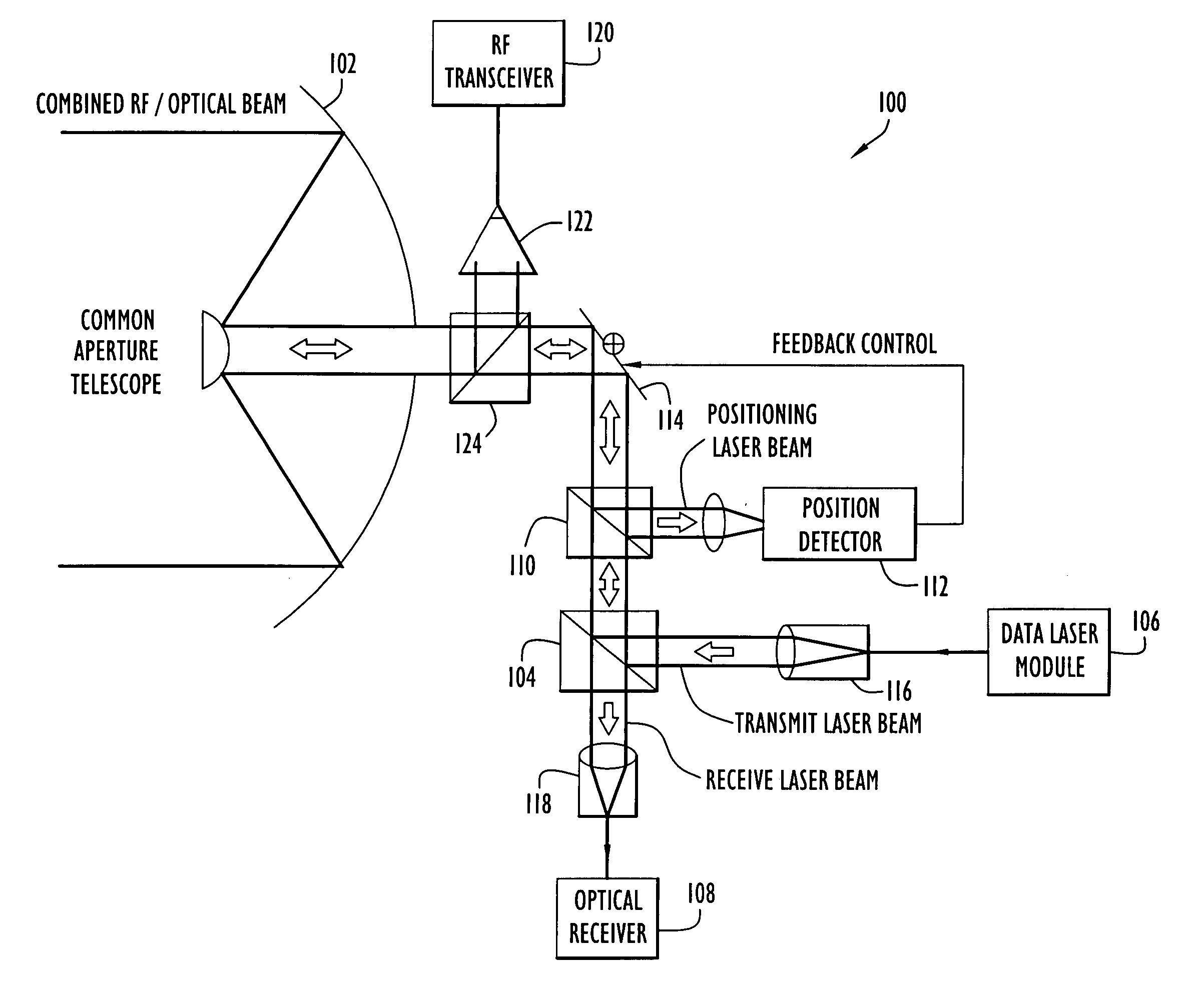
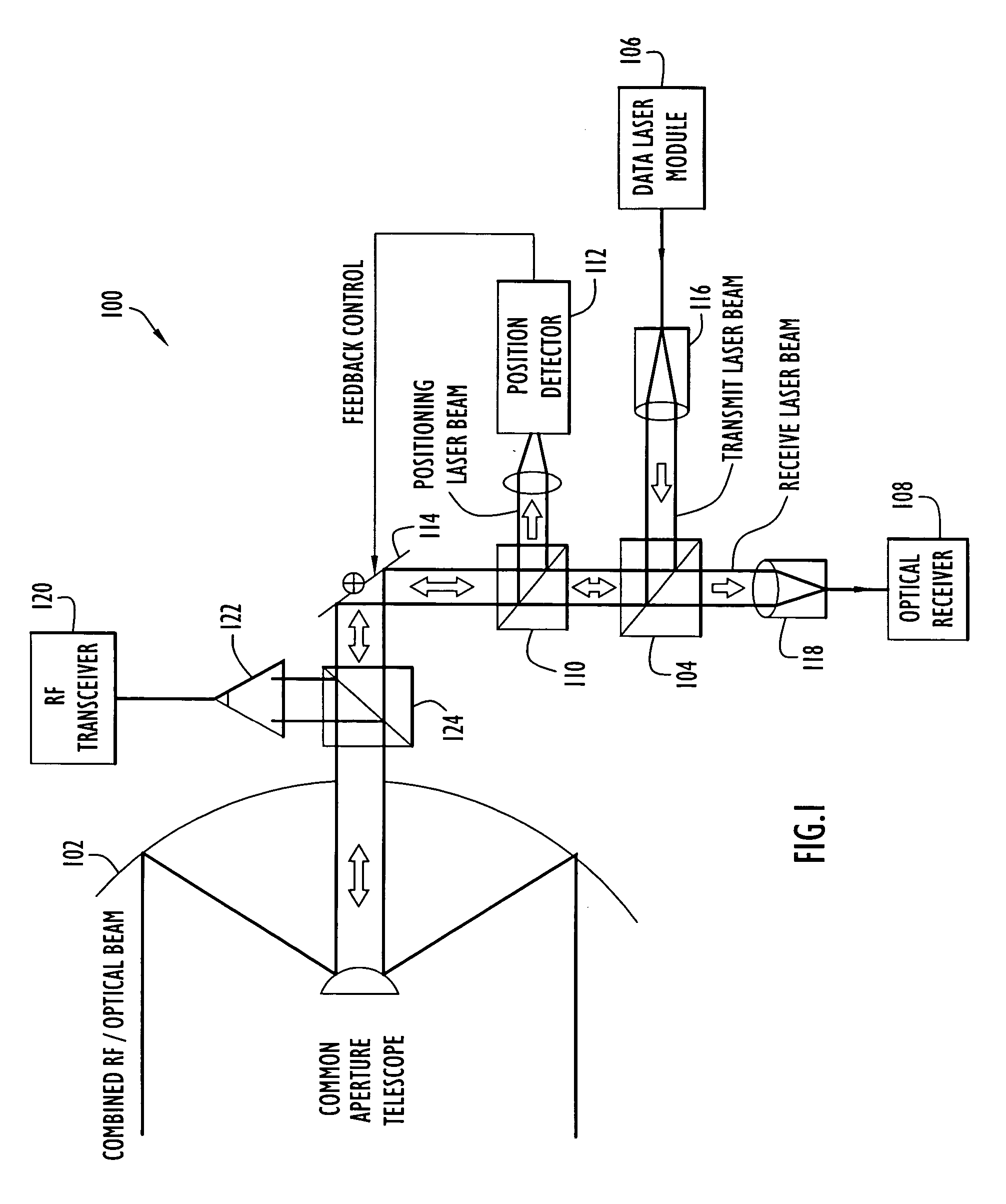
[0021] The following detailed explanations of FIGS. 1-6 and of the preferred embodiments reveal the methods and apparatus of the present invention. A free-space laser communication transceiver architecture according to an exemplary embodiment of the present invention is shown in FIG. 1. The architecture depicted in FIG. 1 is a conceptual diagram illustrating major functional units, and does not necessarily illustrate physical relationships.

[0022] Transceiver 100 includes a common aperture telescope 102 that transmits laser beams toward a far-end transceiver and receives laser beams from the far-end transceiver to effect two-way communication. Preferably, laser beams are transmitted at one wavelength and received at another wavelength such that telescope 102 can simultaneously transmit and receive laser beams. Additionally, telescope 102 can receive a laser beam used to determine the angular position of the far-end transceiver, which can be used to control the pointing direction of ...


PUM


Abstract

A free-space communication transceiver includes a telescope for transmitting and receiving laser beams, a tunable laser transmitter for generating a transmit laser beam modulated with data, a tunable optical receiver for processing a receive laser beam received from the telescope to recover data, and a tunable beamsplitter that directs the transmit laser beam to the telescope and directs the receive laser beam from the telescope to the optical receiver. Between the telescope and beamsplitter, the transmit and receive laser beams travel along a common optical axis as collinear collimated free-space beams. The transmit and receive laser beams operate at different wavelengths that can be interchanged, thereby support full-duplex operation. The beamsplitter employs a tunable etalon filter whose wavelength-dependent transmission characteristics are adjusted according to the transmit and receive wavelengths. Optionally, RF signals can additionally be couple to the common optical axis and transmitted and received by the telescope.

Description

BACKGROUND OF THE INVENTION [0001] 1. Field of the Invention [0002] The present invention relates to a communication transceiver architecture and, more particularly, to a full-duplex free-space laser communication system. [0003] 2. Description of the Related Art [0004] Free space laser communication systems offer the potential to transmit data at very high data rates over long distances. Due to the spatial coherence of laser sources, long range transmission is possible at modest power levels compared to RF systems. Further, the modulation frequencies of lasers allow for gigahertz bandwidths and are limited only by the current state of electro-optic components. [0005] However, operating conditions such as atmospheric turbulence and cloud obscurations affect the performance of free space laser communication systems. Consequently, communication systems relying solely on laser signals at optical wavelengths may suffer periods in which communication is severely diminished or entirely pre...

Claims


Application Information

Patent Timeline
Patent Type & Authority Applications(United States)
IPC IPC(8): H04B10/00H04B10/118
CPCH04B10/118H04B10/1125H04B7/18506
Inventor FISHER, DONALDGANGL, MICHAEL
Owner PERATON INC
Why Eureka
Try Eureka