Ventilated brake pads

a technology of brake pads and ventilation, which is applied in the direction of brake systems, mechanical devices, transportation and packaging, etc., can solve the problems of brake malfunction, kinetic energy, intense temperature rise, etc., and achieve the effect of improving the exchange surface area, facilitating heat flux transfer, and improving the compromise between ventilation and mechanical strength

Inactive Publication Date: 2007-02-15
FAIVELEY TRANSPORT GENNEVILLIERS
View PDF11 Cites 24 Cited by
  • Summary
  • Abstract
  • Description
  • Claims
  • Application Information

AI Technical Summary

Benefits of technology

[0010] This heat dissipating structure is formed in the pad, either in the carrier plate or in the lining or in both, for example at their interface, and increases the cooling flux either by increasing the exchange surface area between the pad and the surrounding air, or by increasing the thermal conductivity in one or several directions substantially parallel to the friction surface.
[0011] For example, the increase in the heat exchange surface area with the surrounding air may be made by making perforations of oblong holes in the carrier plate and / or the pad, in other words elongated holes typically in the form of cylinders with a cross-section that is not necessarily circular. These holes move along one or several directions substantially parallel to the friction surface. They are through holes such that air can pass through them freely. The exchange surface area may also be increased by forming projections around the periphery of the carrier plate, the said projections being preferably provided with cooling fins oriented along the direction of the moving air. The two solutions—perforations+projections—may advantageously be combined, since the carrier plate and the lining are required to resist high mechanical stresses and cannot be perforated excessively.
[0014] The holes may also correspond to grooves formed on the surface of the lining that will come into contact with the carrier plate and / or grooves formed on the surface of the carrier plate that will come into contact with the lining because the plane of one of these surfaces is usually parallel to the plane of the friction surface. Obviously, grooves could be formed on both surfaces such that they are facing each other when the lining and the carrier plate are assembled and thus form larger cavities, more easily accessible to moving air. The grooves have the advantage that they can be made by means other than drilling in body. Thus, a larger number of channels can thus be made without too much difficulty, increasing the exchange surface area. A larger number of channels with a smaller diameter but large enough for moving air to pass freely through them provides a better compromise between ventilation and the mechanical strength.
[0015] The carrier plate may also be provided with projections around its periphery. In this case, these projections are limited to the available volume; they must not come into contact with the disc or part of the stirrup, or even with the piston housing, during the movement of the pad imposed by the piston. Preferably, these projections are extensions of the carrier plate substantially along the plane of the carrier plate at its periphery. Depending on the available volume, these extensions can be fitted with fins that are substantially perpendicular to the plane of the pad and are oriented along a direction substantially parallel to the direction of the moving air at the pad. The plane of the carrier plate is usually parallel to the plane of the friction surface and the increase in the metallic mass in the plane of the carrier plate and near its periphery facilitates transfer of heat flux by conduction parallel to the plane of the friction surface, this flux being higher when these projections are actively cooled by moving air.
[0016] The increase in thermal conductivity in one or several directions substantially parallel to the plane of the friction surface may for example be increased by providing the brake lining and / or the carrier plate with bars made of a material conducting heat better than the material from which the lining and / or the carrier plate that contains these bars is made. Thus, oblong holes can be formed in the said pad and / or the said carrier plate as described above and these holes can then be filled with bars that are good conductors of heat. These holes may be either perforated in body, or machined in the form of grooves on the surface that acts as an interface between the carrier plate and the lining. As above, the carrier plate and the lining may be provided with facing grooves. The perforations thus obtained are filled with bars with a complementary shape composed of a material that is a good conductor of heat, typically copper bars. Cooling by ambient air is preferred, for example using hollow bars that pass from one side of the pad to the other. These bars can also be extended such that they are longer than the housings formed in the pad to contain them and they can be provided with a projection, typically cooling fins, to increase their exchange surface area. This arrangement improves the transfer of a heat flux by conduction parallel to the plane of the friction surface, this flux being greater when the bars are extended by projections actively cooled by moving air.
[0017] The heat dissipating structure characteristic of this invention may advantageously be combined with heat shields according to prior art that in particular will protect the brake cylinder, the braking fluid and the piston.

Problems solved by technology

The reduction in kinetic energy of the rotating assembly requires large friction forces that can cause intense temperature rise at the contact between the lining and the disk.
These temperature rises can cause malfunctions of the brake (degradation of the lining material, poor leak tightness at the contact between the piston and its housing, boiling and / or degradation of the braking fluid, etc.).

Method used


Image

  • Ventilated brake pads
  • Ventilated brake pads
  • Ventilated brake pads

Examples


example 1

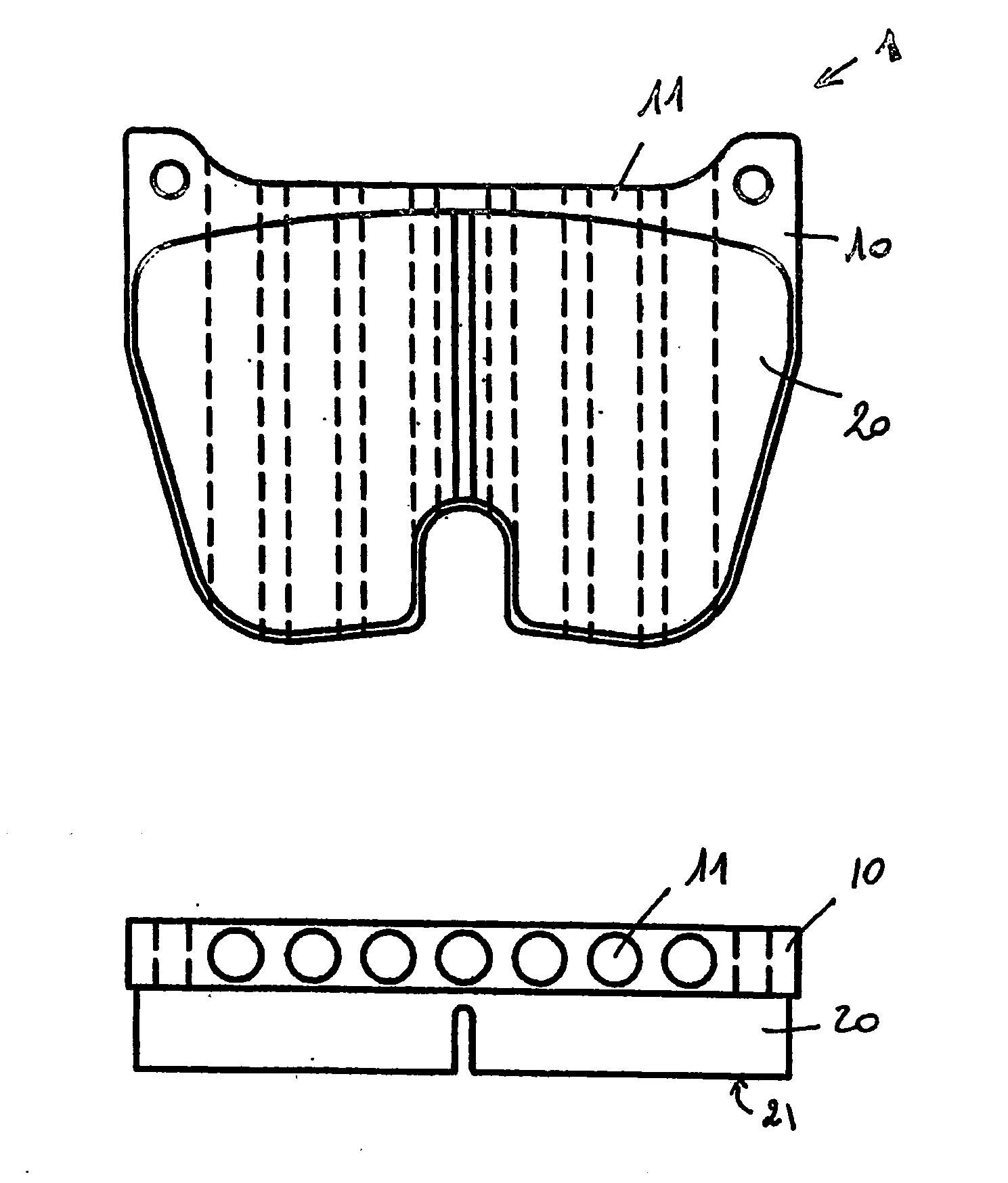
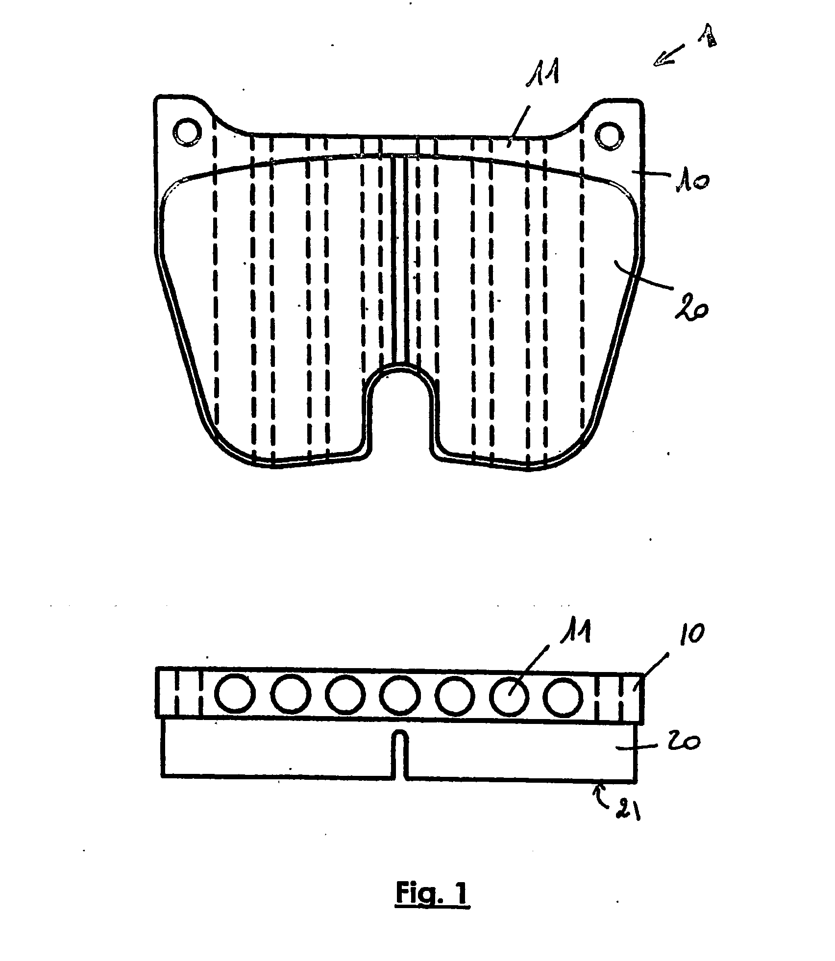
Pad with a Perforated Carrier Plate (FIG. 1)

[0024]FIG. 1 shows a disc brake pad 1 with a steel carrier plate 10 and a sintered brake lining 20 that has a plane surface 21 that will come into friction contact on one face of the disk, called the friction surface. The brake lining 20 is fixed to the carrier plate 10 by brazing.

[0025] The heat dissipating structure is obtained by perforating holes 11 in the carrier plate 10 along a direction substantially parallel to the friction surface 21. These holes are through holes; they pass through the carrier plate 10 from one side to the other such that air can pass through them freely. They are cylindrical holes parallel to each other and with an axis substantially parallel to the plane of the friction surface. These holes are oriented parallel to the air inlet.

[0026] The thickness of the carrier plate 10 is typically 8 mm and it is inscribed within an substantially 80*60 mm rectangle. The diameter of the seven holes 11 is 6 mm, so that th...

example 2

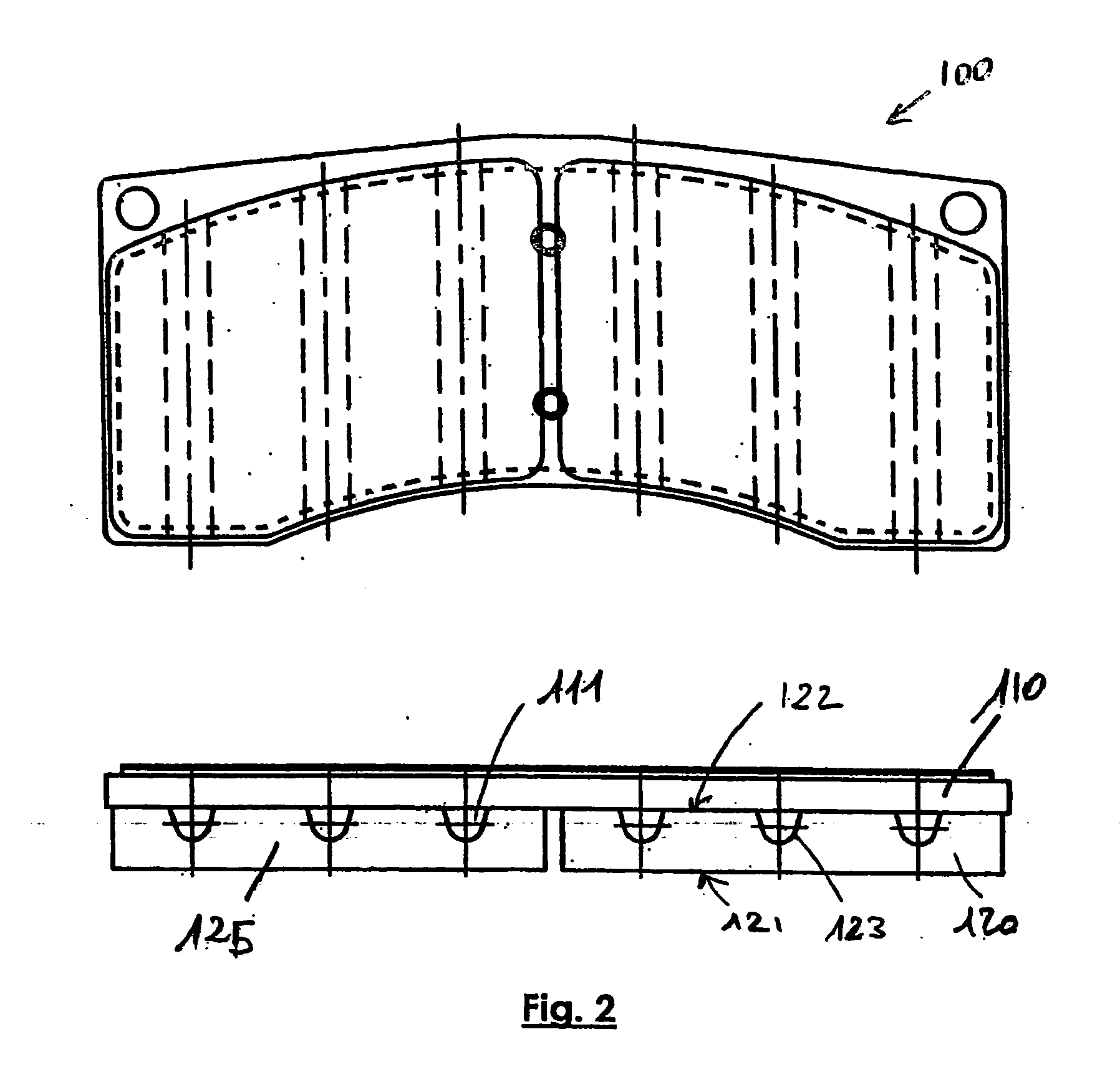
Pad with a Ventilated Lining (FIG. 2)

[0027]FIG. 2 shows a disc brake pad 100 with a shape different from the above. It also includes a steel carrier plate 110 and two sintered brake linings 120 and 125. The linings have a friction surface 121, with a total extent about 70% greater than the extent of the friction surface of the lining in example 1. The brake linings 120 and 125 are fixed to the carrier plate 110 by brazing.

[0028] In this example, the heat dissipating structure has been formed in the brake lining 120 (or 125) or more precisely at the contact between the brake lining and the carrier plate. Linear grooves 123 parallel to each other have been made on the surface 122 of the lining opposite the friction surface 121, along a direction substantially parallel to the friction surface 121. Once the brake lining 120 (or 125) has been assembled to the carrier plate 110, the grooves 123 and the wall of the carrier plate form holes 111 parallel to each other, passing through the ...

example 3

Pad with a Ventilated Lining and a Carrier Plate with a Peripheral Projection Fitted with Cooling Fins (FIG. 3)

[0030]FIG. 3 shows a disc brake pad 200 with a steel carrier plate 210 and a sintered brake lining 220 that is provided with a friction surface 221. The brake lining 220 is fixed onto the carrier plate 210 by brazing.

[0031] As in the previous example, the heat dissipating structure has been formed in the brake lining 220, or more precisely at the contact between the brake lining and the carrier plate. Linear grooves 223 parallel to each other were formed on the surface 222 of the lining opposite the friction surface 221 along a direction substantially parallel to the friction surface 221. Once the brake lining 220 has been assembled to the carrier plate 210, the grooves 223 and the wall of the carrier plate form holes 211 parallel to each other, passing through the pad from one side to the other such that air can pass freely through them. The axis of these holes is substa...


PUM


Abstract

A disc brake pad including a brake lining having at least one friction surface, and provided with a heat dissipating structure which circulates the heat to be dissipated in one or more directions substantially parallel to the plane of the friction surface. The structure is arranged in the lining and / or in a carrier plate if there is one, or at the interface. The structure may be formed from cylindrical holes with axes following one or more directions substantially parallel to the friction surface. These holes are through holes, such that the air can freely pass therethrough. The structure may also be formed from projections at the periphery of the carrier plate, optionally fitted with cooling fins, or bars which are good heat conductors enclosed a component of the pad.

Description

FIELD OF THE INVENTION [0001] This invention relates to disc brake linings, and more precisely to disc brake pads. Pads are disc brake elements generally located on each side of the disk, grouped in a stirrup straddling over the edge of the disk. Each pad is associated with one or several brake pistons. They are actuated by this or these pistons and are moved by the pressure of the braking fluid such that they come into contact with the disc surface, the disc typically being fixed to a vehicle wheel or a machine flywheel (wind generator, conveyor belt, etc.). The resulting friction reduces the rotation speed of the assembly. DESCRIPTION OF RELATED ART [0002] The disc brake pads comprise a lining that is a wear element designed to come into contact with a face of the disc and a carrier plate, usually made of a different material, that will fix the stirrup and the brake pads together. The element that fixes the stirrup and the pads is occasionally a part of the lining and machined in ...

Claims


Application Information

Patent Timeline
Patent Type & Authority Applications(United States)
IPC IPC(8): F16D65/827F16D65/092F16D65/78
CPCF16D65/092F16D2065/788F16D65/78
Inventor THEMELIN, LUCCOTTIN, JEAN-CLAUDEMACE, HERVEDEPREZ, DELPHINELELIEVRE, LOIC
Owner FAIVELEY TRANSPORT GENNEVILLIERS
Why Eureka
Try Eureka