
Continuous chamber mass confinement cells and methods of use thereof

a technology of confinement cells and chambers, which is applied in the direction of mining structures, artificial islands, excavations, etc., can solve the problems of water, etc., and affecting the sand retention wall's ability to withstand sunlight, wind and water

Inactive Publication Date: 2007-02-15
NEW TECH RESOURCES
View PDF39 Cites 21 Cited by
  • Summary
  • Abstract
  • Description
  • Claims
  • Application Information

AI Technical Summary

Benefits of technology

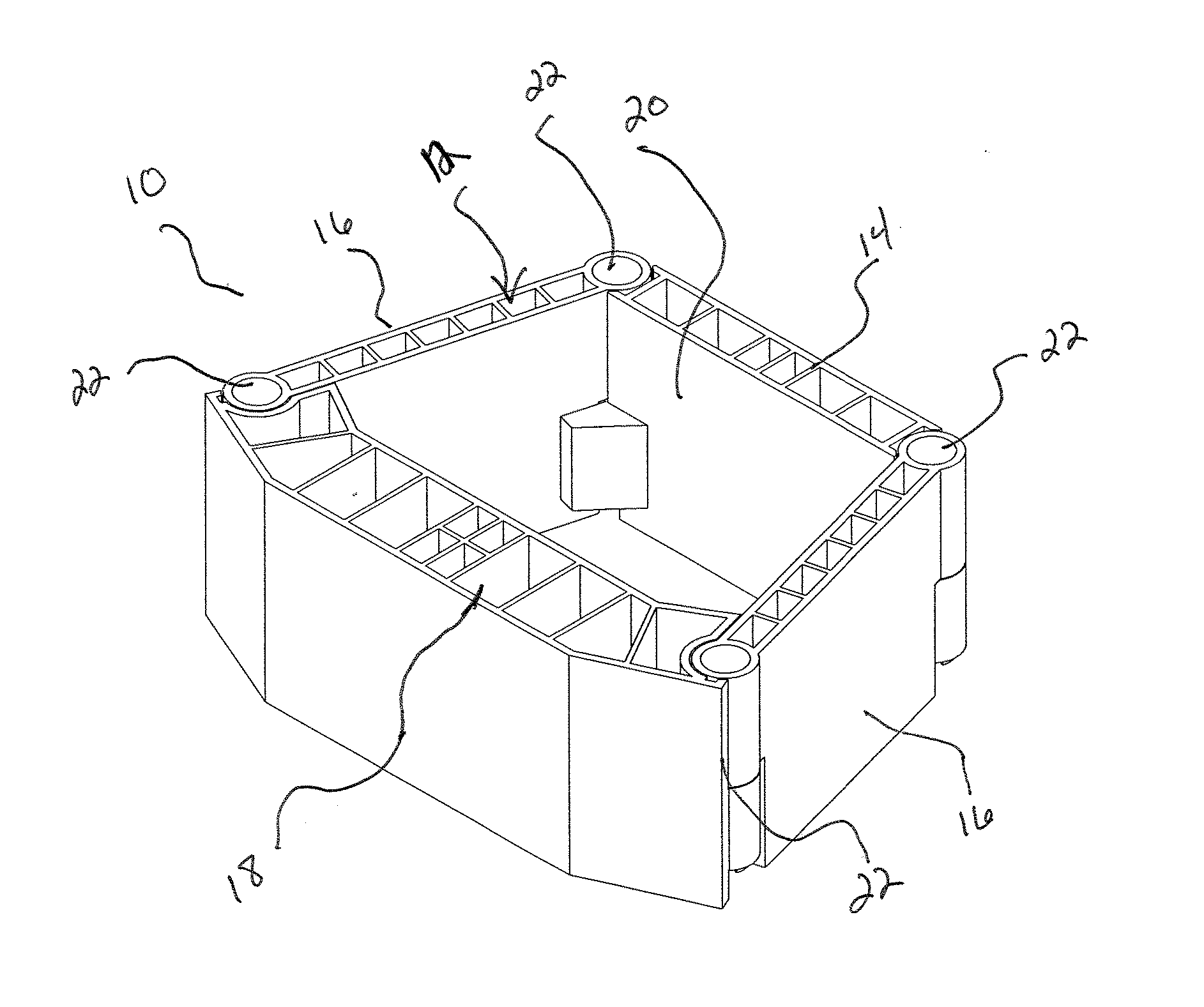
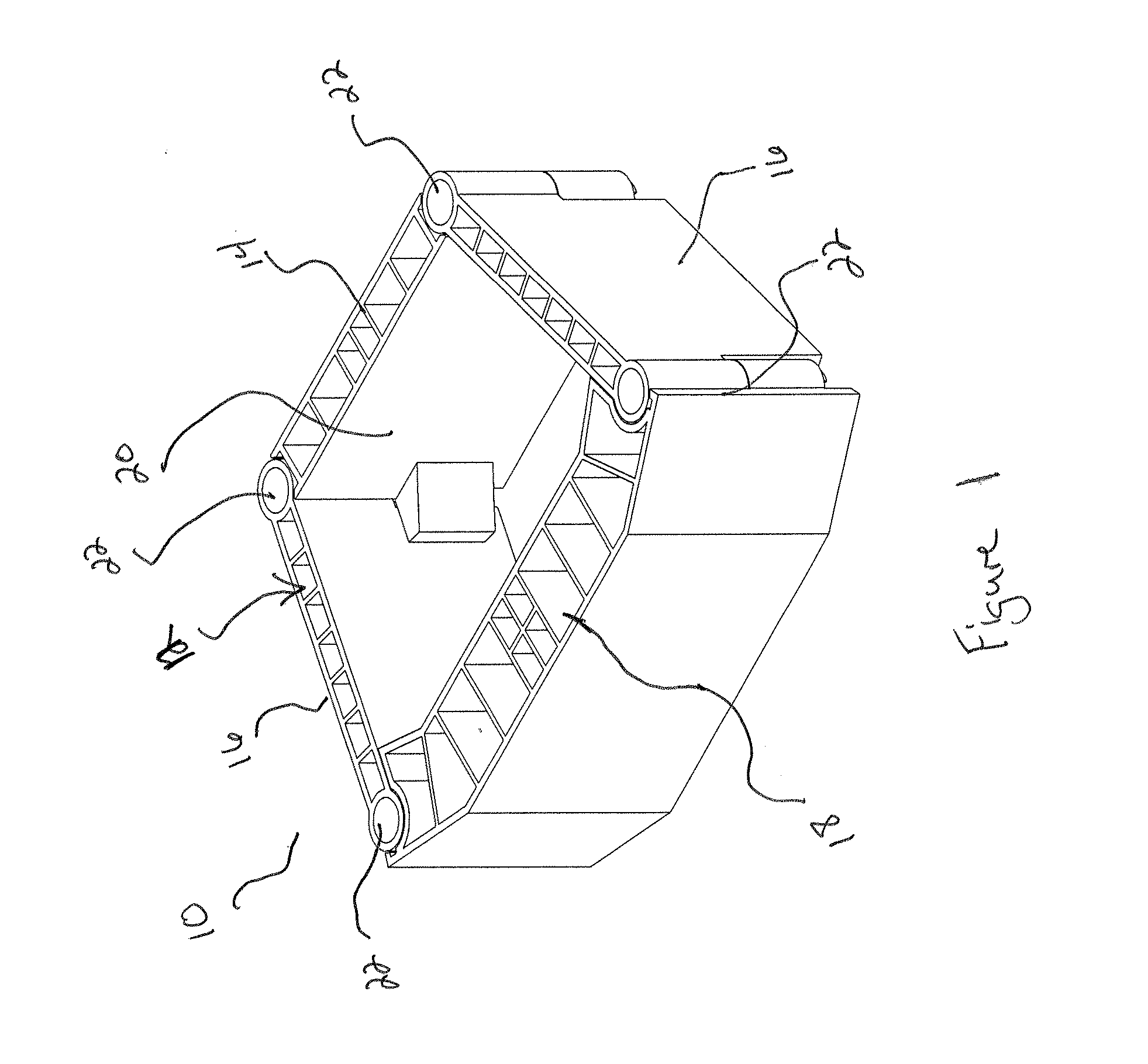
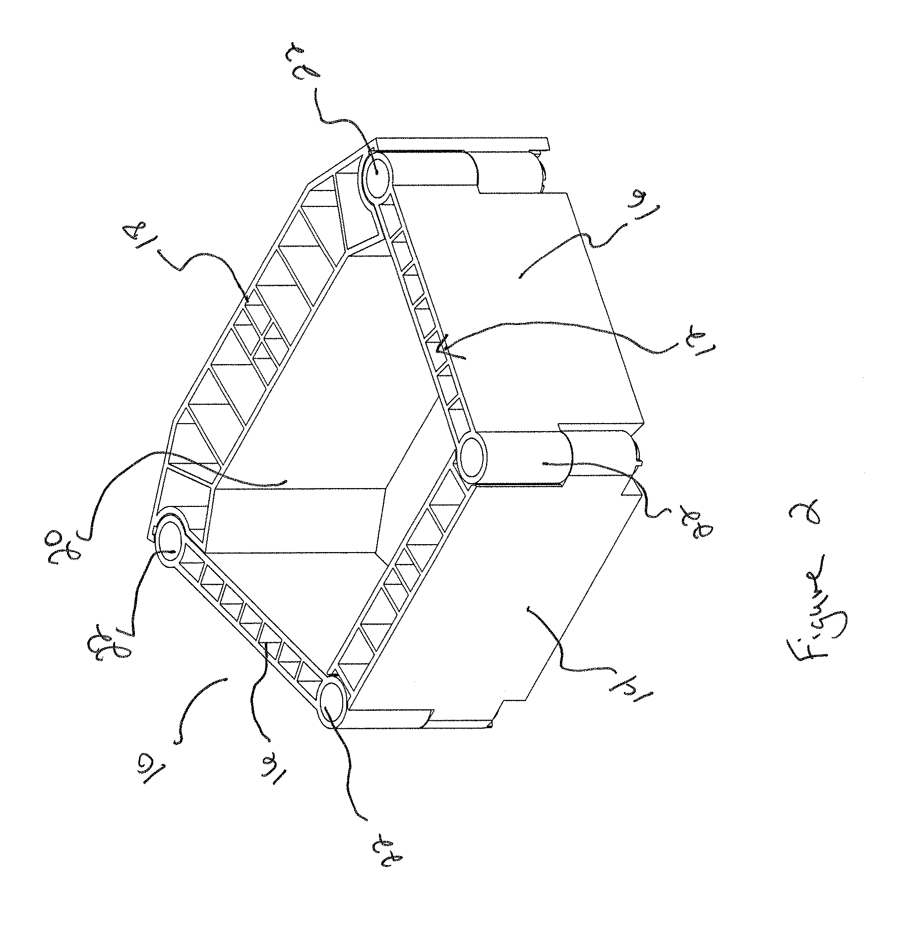
[0009] Embodiments of the present invention relate to retaining wall products including mass confinement cells that are resistant to damage and wear caused by the environment. The mass confinement cells generally include a frame adjoined to one or more enclosing members to form a continuous chamber, which allows the flow of fill material to adjacent confinement cells below and above. The deterioration resistant mass confinement cell is generally a hollowed frame or shell that includes a deterioration resistant material that is light-weight and is configured to interlock with adjacent confinement cells, thereby forming a continuous chamber system capable of accepting and retaining any type of filling material. The filling material provides weight, density, structure and stability to the mass confinement cells and also ultimately provides stability and security to the retaining wall constructed of such cells.
[0010] Various embodiments of the deterioration resistant mass confinement cells of the present invention comprise a frame adjoined with one or more chamber enclosing members to form a mass confinement cell having a continuous flow chamber. The frame in various embodiments of the present invention may include two or more panels that are hingedly adjoined to allow the panels to position in a flattened configuration, thereby providing transportation and storage efficiencies. In various embodiments at least two of the panels extend from the front of the cell to the back of the cell at angles (e.g. less than 90°), thereby allowing for the back of the cell to be shorter in length than the front of the cell. This configuration allows for curving of walls or revetments when constructing a wall. The continuous flow chamber of these mass confinement cells generally forms a series of integrated channels when placed in a wall or earth retention structure, thereby allowing the flow of fill material between adjacent confinement cells.
[0011] The cells of the present invention may further include one or more anchoring devices for securing each cell to adjacent cells or securing them into position in the retaining wall. In various embodiments of the present invention one or more of the panels include one or more locking pegs or peg extensions for interconnecting the stacked confinement cells. The locking pegs or peg extensions assist in positioning and / or adjoining adjacent cells and facilitating the flow of fill material to the adjacent cells. Additionally, the locking pegs or peg extensions assist in retaining the fill material within the adjoined confinement cells and also may lock the adjacent cells to each other. As previously suggested, the continuous chambers are adapted for receiving and retaining fill materials, such as sand, dirt, gravel, pea rock, class V, concrete or any other similar material, which provides the permanent weighting and stability of each retaining wall cell.

Problems solved by technology

However, many of the materials utilized in the construction of retaining walls are susceptible to deterioration, heavy, cumbersome and / or not very aesthetically appealing.
The ability of these retaining walls to withstand sunlight, wind, water, general erosion and other environmental elements is a problem with most retaining wall products.
Leaving the shoreline natural can lead to erosion, cause an unmanageable and unusable shoreline, create high maintenance, and potentially destroy an aesthetically pleasing property.
Many materials utilized in retention of shorelines are subject to immediate deterioration and / or are not as aesthetically appealing as one would desire.
Furthermore, many materials utilized on shoreline structures are difficult to maintain due to the awkward location in the water and also the prevalent growth and presence of organic materials that can get caught and flourish in such a structure.
One problem with waterfront properties that use a continuous wall of typical riprap is the shoreline will retain some organic material, will accumulate additional organic material brought in by the water and / or will allow vegetation to grow within the openings between stones.
This usually leads to an unmanageable and aesthetically displeasing shoreline or higher maintenance.
Furthermore, the riprap is never uniform in color and size and therefore does not provide the most aesthetically pleasing shoreline or complete coverage of the shoreline.
The lack of uniform shoreline coverage allows for some erosion, collection of unwanted materials and the potential growth of undesirable vegetation.
Another problem with materials normally utilized in the construction of retaining walls, such as poured in place concrete, masonry, landscape timbers, railroad ties or dry-cast blocks (e.g. blocks produced by Keystone® Inc. or Anchor® Retaining Wall Systems, Inc.) is that regulations in most states and counties prohibit their use in or near bodies of water because of the potential chemical diffusion into the body of water and / or the crumbling or deterioration of the material into the body of water over time.
Many of these retaining wall materials diffuse chemicals, dissolve, crumble, break apart and / or float into the body of water of which they are lining, thereby causing problems with the shoreline and pollution of the water.
An additional concern that exists in the construction of retaining walls is the weight of the materials.
Concrete blocks (e.g. wet or dry cast), large or medium size stones or timbers can be heavy and cumbersome to move into the wall location and maneuver when constructing retaining walls and earth retention systems.
Many locations for which retaining walls are constructed are positioned in awkward terrain.
Therefore, heavy building materials are difficult to move into such locations and furthermore are difficult to position when constructing the retaining wall, thereby adding additional cost and labor for installation.

Method used


Image

  • Continuous chamber mass confinement cells and methods of use thereof
  • Continuous chamber mass confinement cells and methods of use thereof
  • Continuous chamber mass confinement cells and methods of use thereof

Examples


example 1

[0163]

HIGH SOLIDS ALLPHATIC POLYURETHANE120 SeriesDESCRIPTIONHigh Solids 3.5 V.O.C. two component polyurethane for metal, plastic,and interior wood. It is used for industrial and automotive applications.This system has excellent chemical and stain resistance. It has shownexcellent adhesion to many substrates with good mar and abrasionresistance and it has 2-3H hardness.CHARACTERISTICSDensity - lbs / gal:7.95-13.0Solids, wt. %:51-70Solids, volume:42.9-60Viscosity:35-42 Sec.Flash Point ° F.80Application Method:Conventional of HVLPReduction for Application:5-base; 1-XL009; 1-acetone6-base; 1-XL003; 1-20LT161Pot Life:3-HRS @ 70° F.Cure Schedule:30 min @ 180° F.Gloss 60°:Flat to 96VOC as supplied - lbs / gallon:3.0-3.6VOC as applied - lbs / gallon:2.9-3.5

example 2

[0164]

MEDIUM SOLIDS ALLPHATIC POLYURETHANE121 SeriesDESCRIPTIONThe 121 Series is a medium solids, low temperature cure two componentpolyurethane for use on metal and plastic. It is used for industrial andautomotive applications. This system has excellent chemical, stain,and water soak resistance. It has good adhesion to many substrateswith good mar and abrasion resistance and it has 2H hardness.CHARACTERISTICSDensity - lbs / gal:7.92-11.0Solids, wt. %:45-67Solids, volume:37-48Viscosity:45 sec Zahn#2Flash Point ° F.78Application Method:HVLP; Conv.Reduction for Application:4-base; 1-XL0095-base; 1-XL003Pot Life:2 hrs @ 70° F.Cure Schedule:35 min @ 160° F., Air Drytack free 40 minGloss 60°:Flat to 96VOC as supplied - lbs / gallon:3.6-4.3VOC as applied - lbs / gallon:3.37-4.0

Both polymer adhesion paints of Examples 1 and 2 are manufactured and distributed by:


PUM


Abstract

The present invention relates to mass confinement cells that may be used in retaining walls and earth retention systems that has a natural earthen appearance or other aesthetic design and is resistant to damage and wear caused by the environment. The mass confinement cells are generally light-weight and include a continuous chamber that at least partially aligns with confinement cells positioned above and below, thereby allowing the intermingling of fill material between adjacent cells. The mass confinement cells are capable of accepting and retaining any type of filling material. The filling material provides weight, stability and security to a retaining wall constructed of such mass confinement cells.

Description

CROSS-REFERENCE TO RELATED APPLICATION [0001] This application claims priority to U.S. Provisional Application Ser. No. 60 / 707,032, filed on Aug. 10, 2005, U.S. Provisional Application No. 60 / 741,737 filed on Dec. 2, 2005, and U.S. Provisional Application No. 60 / 777,617 filed on Feb. 28, 2006. The contents of the three previously mentioned applications are incorporated by reference herein.FIELD OF THE INVENTION [0002] The present invention relates to environment resistant landscaping products, such as mass confinement cells for retaining wall and earth retention applications, that in various embodiments provide a natural earthen appearance, such as rock, stone, sand, soil, clay, wood, trees and foliage, water, or any other natural earthen appearance. The mass confinement cells may also include a fascia having a natural earthen appearance or other aesthetically appealing design that is resistant to damage and wear caused by the environment. The mass confinement cells are generally li...

Claims


Application Information

Patent Timeline
Patent Type & Authority Applications(United States)
IPC IPC(8): E02D5/00
CPCE02D29/0241E02D29/0266E02D29/025E02D29/02
Inventor KNUDSON, EDWARD ALANDOLAN, JOHN F.RACE, ROBERT J.BENDELL, TIMOTHY PAULLOKHANDE, VISHAL NANASAHEBDARST, DANIELKRAUSE, ERIC JASON
Owner NEW TECH RESOURCES
Learn More