
Battery case having improved thermal conductivity

a battery case and thermal conductivity technology, applied in the field of battery case and alkaline storage battery, can solve the problems of poor tolerance to deep discharge, impractical power source for electric vehicles, hybrid electric vehicles, etc., and achieve the effect of more efficient cooling

Inactive Publication Date: 2007-02-15
BATTERY PATENT TRUST
View PDF4 Cites 42 Cited by
  • Summary
  • Abstract
  • Description
  • Claims
  • Application Information

AI Technical Summary

Benefits of technology

[0012] Preferred embodiments incorporate fins on the exterior of the battery case. The use of fins provides mechanical stability and more efficient cooling. Fins provide additional surface area on the case that aids in the transfer of heat from the interior of the battery.

Problems solved by technology

However, their low energy density (about 30 wh / kg) and their inability to reject heat adequately, makes them an impractical power source for electric vehicles (EV), hybrid electric vehicles (HEV) and 2-3 wheel scooters / motorcycles.
In addition, electric vehicles using lead-acid batteries have sluggish acceleration, poor tolerance to deep discharge, and a battery lifetime of only about 20,000 miles.
For example, in electric vehicles and in hybrid vehicles, the weight of the batteries is a significant factor.
First, ambient heat due to the operation of the vehicle in hot climates; second, resistive or I2R heating on charge and discharge, where I represents the current flowing into or out of the battery and R is the resistance of the battery; and third, a tremendous amount of heat is generated during overcharge due to gas recombination.
Although polymers typically have excellent volume resistivity and dielectric properties, poor thermal conductivity is a drawback.

Method used


Image

  • Battery case having improved thermal conductivity
  • Battery case having improved thermal conductivity
  • Battery case having improved thermal conductivity

Examples


Embodiment Construction

[0039] The present invention discloses a battery and battery case having improved thermal conductivity. The battery case may be formed from a first polymeric material and a second polymeric material, wherein the second polymeric material has a higher thermal conductivity than the first polymeric material. The differing thermal conductivity promotes the transfer of heat away from the battery cell(s). Additionally, by strategic placement of the thermally conductive material, the overall weight of the system is not dramatically increased and heat transfer is maximized.

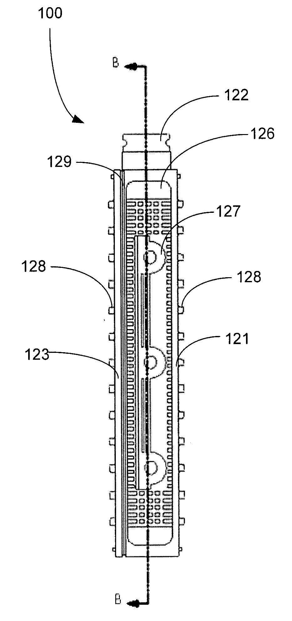
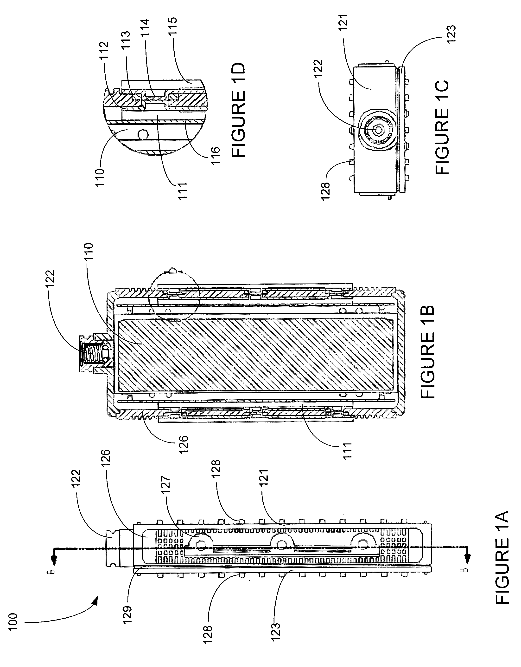
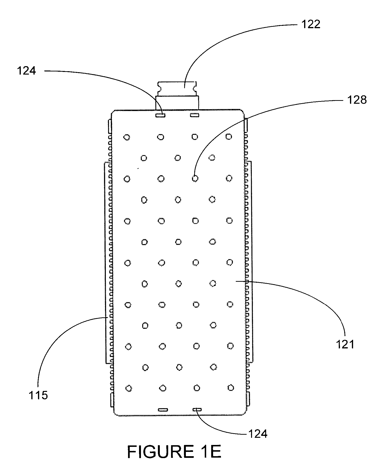
[0040] Referring to FIGS. 1A-1E, an embodiment of a battery, generally referred to as 100, of the present invention is illustrated. A first polymeric material comprises a battery enclosure on the top 121A and bottom 121B and a battery cover on the front 123A and back 123B. A second polymeric material comprises thermally conductive side walls 126A and 126B. In this embodiment, the thermally conductive side walls 126A and ...


PUM


Abstract

The present invention discloses is a battery case, comprising a base case and an insert as two parts of the exterior case. The base case is formed of a first polymeric material and the insert is formed of a second polymeric material, wherein the second polymeric material has a higher thermal conductivity than the first polymeric material. The second polymeric material may comprise a base polymer and at least one thermally conductive filler, such as ceramic, glass or carbon fiber. The base polymer of the second polymeric material may be selected from the group consisting of polyphenylene ether, polystyrene, polypropylene, polyphenylene sulfide and the ceramic filler may be selected from the group consisting of alumina, fused silica, a glass ceramic sold under the trademark MACOR®, boron nitride, silicon nitride, boron carbide, aluminum nitride, silicon carbide, zirconia and combinations thereof. The first polymeric material may be selected from the group consisting of polyphenylene ether, polystyrene, polypropylene, polyphenylene sulfide. The base case and insert may be integrally molded by one of two-color molding and insert molding with the first polymeric material and the second polymeric material. The battery case of the present invention may comprise a monoblock alkaline storage battery case.

Description

FIELD OF THE INVENTION [0001] The present invention relates to a battery case having improved thermal conductivity and an alkaline storage battery. More particularly, the present invention relates to a battery case and an alkaline storage battery that includes a thermally conductive polymeric material, wherein the polymeric material allows for the transfer of heat away from the battery and battery case. BACKGROUND OF THE INVENTION [0002] Rechargeable batteries are used in a variety of industrial and commercial applications such as fork lifts, golf carts, uninterruptible power supplies, and electric vehicles. [0003] Rechargeable lead-acid batteries are a useful power source for starter motors for internal combustion engines. However, their low energy density (about 30 wh / kg) and their inability to reject heat adequately, makes them an impractical power source for electric vehicles (EV), hybrid electric vehicles (HEV) and 2-3 wheel scooters / motorcycles. Electric vehicles using lead-ac...

Claims


Application Information

Patent Timeline
IPC IPC(8): H01M2/02H01M50/10H01M50/124H01M50/131H01M50/209
CPCH01M2/02H01M2/0257H01M2/0295H01M2/1072H01M10/28Y02E60/124H01M10/5016H01M10/504H01M10/5046H01M10/5065H01M2002/0297H01M10/5004H01M10/625H01M10/653H01M10/6551H01M10/613H01M10/6562Y02E60/10H01M50/10H01M50/131H01M50/209H01M50/124
Inventor ANANTHARAMAN, SATISH
Owner BATTERY PATENT TRUST
Learn More