Water separation system

a technology of water separation system and water filter, which is applied in the direction of separation process, gravity filter, feed/discharge of settling tank, etc., can solve the problems of impeded sight-glass function, and achieve the effect of convenient disposal

US20070039883A1Inactive Publication Date: 2007-02-22GLYNN DONALD R
4 Cites 10 Cited by

Patent Information

Authority / Receiving Office
US · United States
Patent Type
Applications(United States)
Current Assignee / Owner
Publication Date
2007-02-22
Estimated Expiration
Not applicable · inactive patent

Smart Images

  • Figure 1
    Figure 1
  • Figure 2
    Figure 2
  • Figure 3
    Figure 3
Patent Text Reader

Abstract

Waste oily water is dewatered by expelling water through ceramic ultra filtration membranes of a cross-flow filter, located in a circulation ring, which is routinely cleaned in situ. The ring has two auxiliary reservoirs, with removable sight glasses, between which reservoirs the cleaning fluid is see-sawed during cleaning cycles, the reversing chemical flow being controlled by float switches. Heating for cleaning purposes is by way of closed-loop high-rate ring circulation. Frequent automated cleaning by a Programmable Logic Controller (PLC) maintains high flux rates with sustainable large volume annual throughput in the range of 1 to 2 million litres per year per square meter of filter membrane surface area. The system is fail-safe and environmentally friendly.
Need to check novelty before this filing date? Find Prior Art

Description

[0001] This application is a continuation-in-part of application Ser. No. 10 / 733,331 filed Dec. 12, 2003, which is a continuation-in-part of application Ser. No. 10 / 050,712 filed Jan. 18, 2002, which are both directed to a system comprising a method and apparatus for separating oil and water from industrial oily wastewaters, and are both incorporated herein by way of reference. In particular, the present system is directed to the separation of water from machining cutting coolant oils, die release agents, oily wash waters, and other emulsified oils, wherein the filter element is systematically and economically cleaned.STATEMENT REGARDING FEDERALLY SPONSORED RESEARCH OR DEVELOPMENT

[0002] NOT APPLICABLE BACKGROUND OF THE INVENTION

[0003] The above-identified prior Application which is incorporated herein by way of reference, teaches of the present need for the provision on-site of effective systems for the economic separation of water from oily wastewater. The prior applications also...

Examples

Embodiment Construction

[0088] In the following description, the term “normally-closed” indicates that in a power-off condition the valve in question would close. Correspondingly the term “normally-open” indicates that in a power-off condition the valve in question would open.

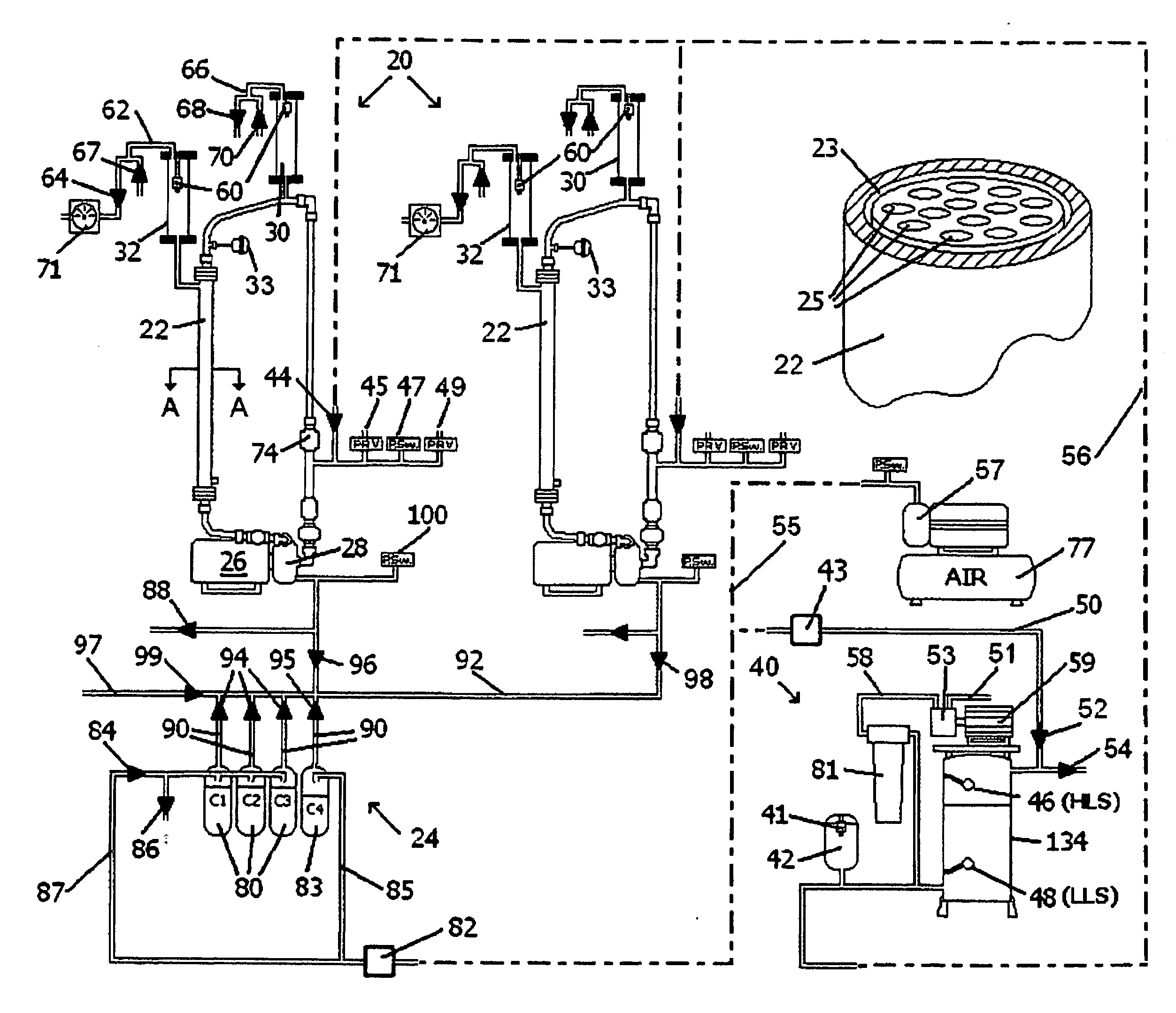
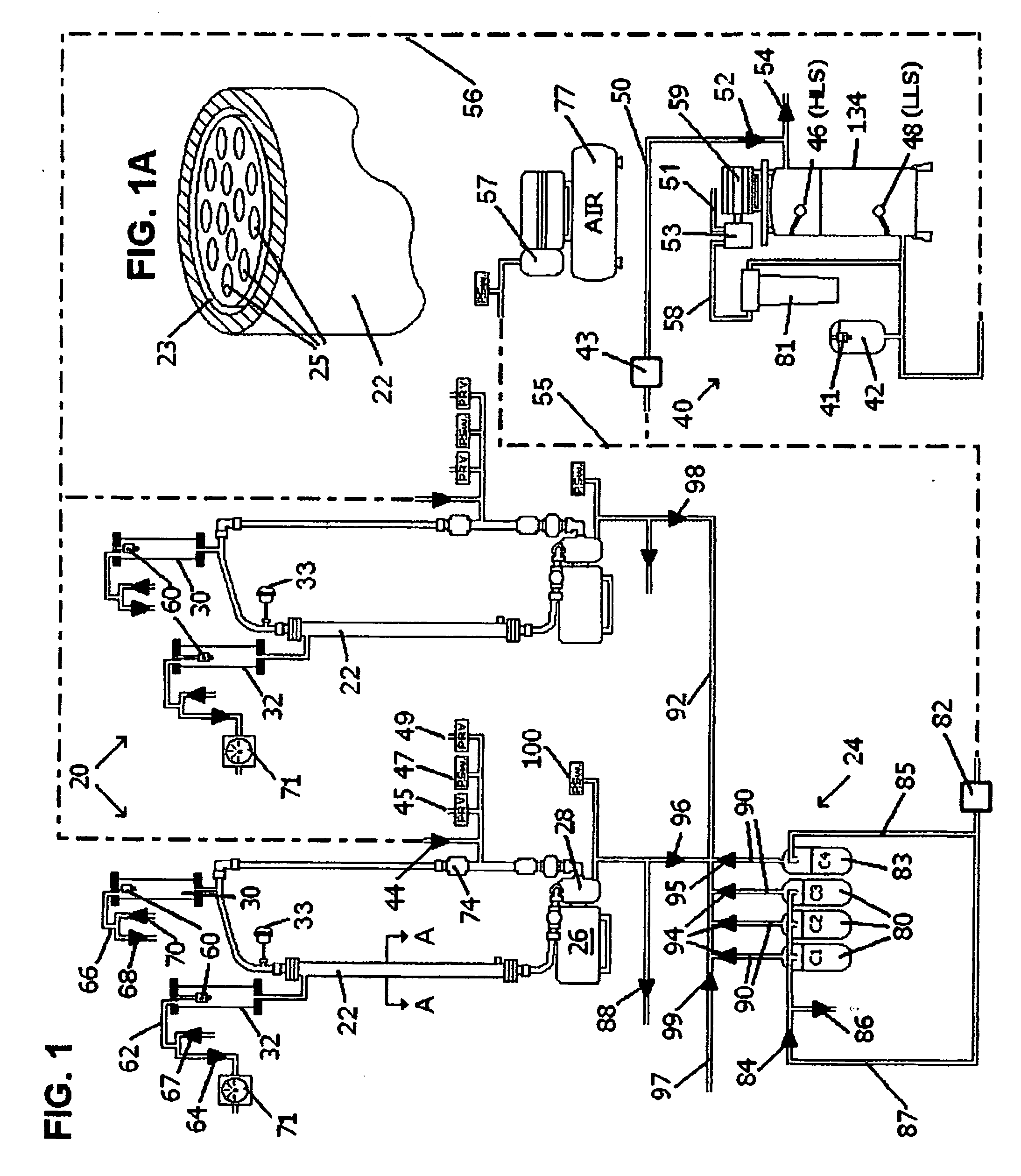
[0089] Referring to FIG. 1, two rings 20 are shown, each having a single filter unit 22. The rings 20 are generally housed within the same cabinet (not shown) and are serviced from a series 24 of cleaning liquids, C1 through C4. The description and numerals applied to the left hand ring 20 are generally identical for the right hand ring 20.

[0090] In FIG. 1A, the location of the lumens within the filter 22, and their membrane filter coatings 25 are shown, together with the permeate water (filtrate) collection annulus 23.

[0091] Each ring 20 includes an electric motor 26 driving a ring re-circulation pump 28, which normally circulates oily water through the central lumens 25 of the filter 22 (see FIG. 1A) and around the ring 20. Each ...