
Water treatment using magnetic and other field separation technologies

a magnetic and field separation technology, applied in magnetic separation, separation processes, filtration separation, etc., can solve the problem of not effectively removing fine pollutant particles, and achieve the effect of simple design, low cost and simple cost structur

Inactive Publication Date: 2007-02-22
CORT STEVEN L
View PDF21 Cites 45 Cited by
  • Summary
  • Abstract
  • Description
  • Claims
  • Application Information

AI Technical Summary

Benefits of technology

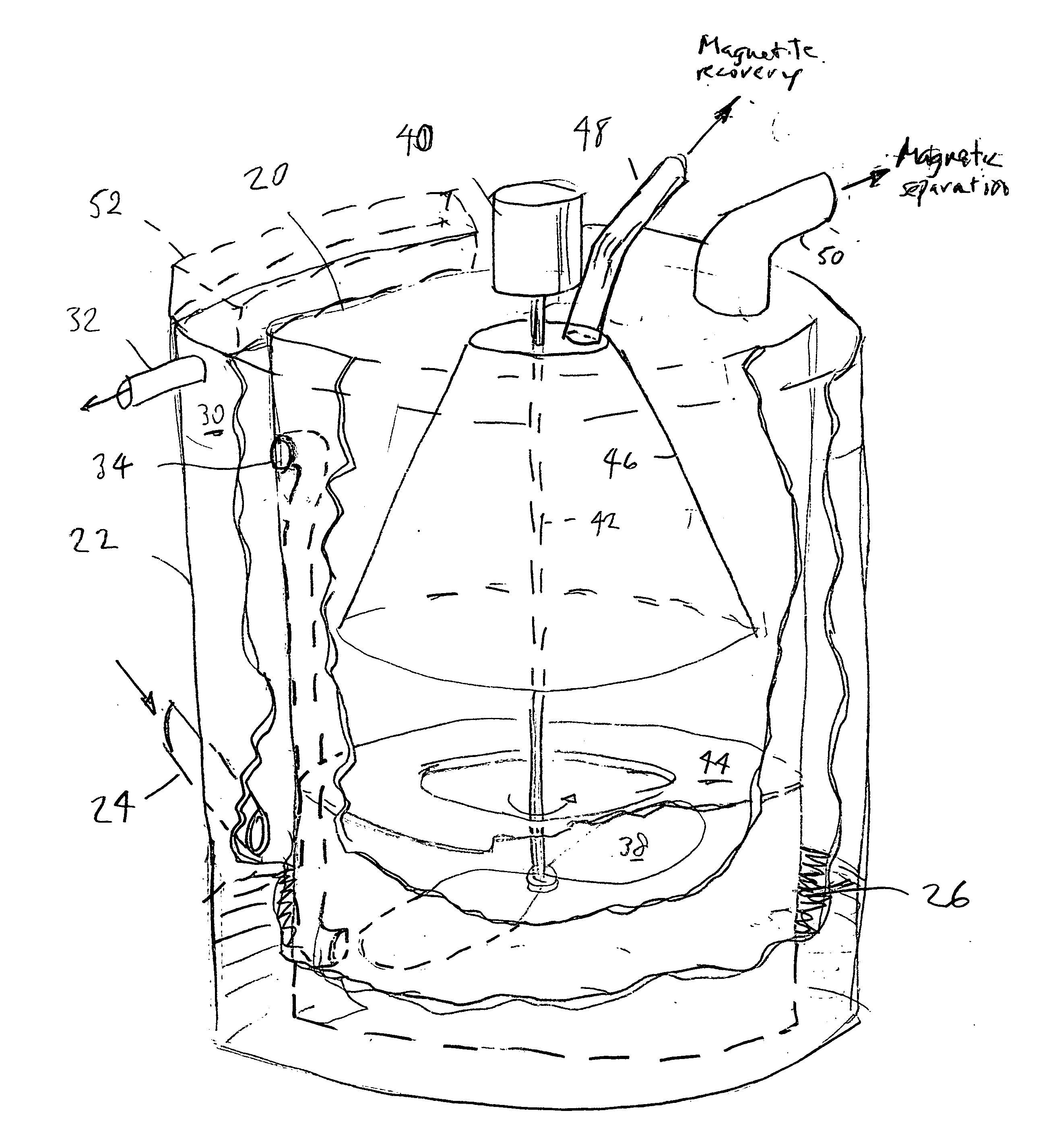
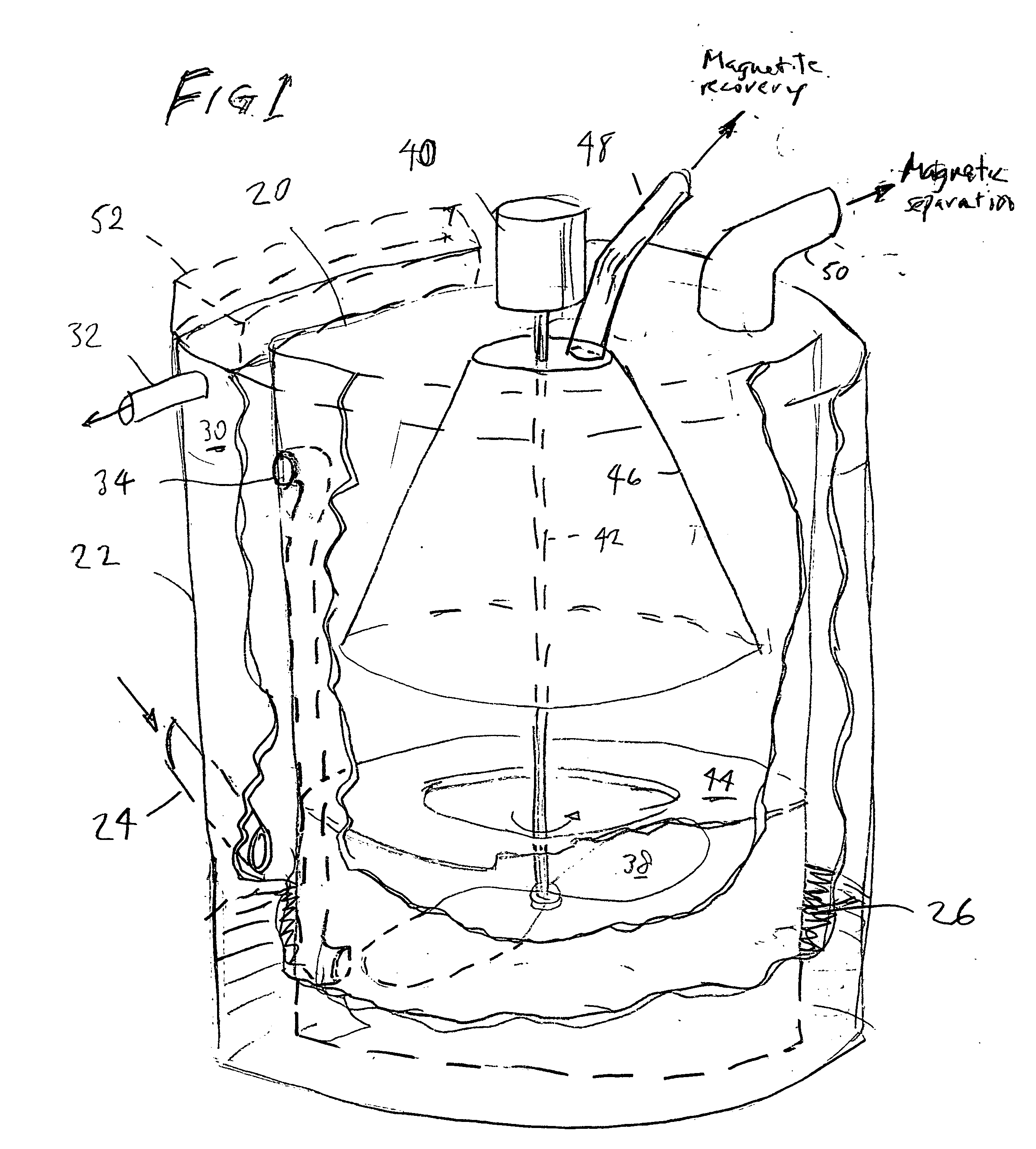
[0013] In one embodiment, the water stream to be treated, along with a quantity of magnetite and a flocculant polymer, is introduced at the lower extremity of a tank with a vortex separator above. Composite magnetic particles including the fine pollutant particles to be removed are thus formed first. The vortex separator causes a spiral upward flow to take place. The composite particles including magnetite are segregated because of the velocity differences in the vortex; that is, the more dense composite particles move to the center of the tank while the clear water moves to the edge of the tank, allowing the particle-laden and clear streams to be readily separated. Magnetic separation can then be performed on the clarified stream to remove any magnetic particles not separated out in the vortex separator.
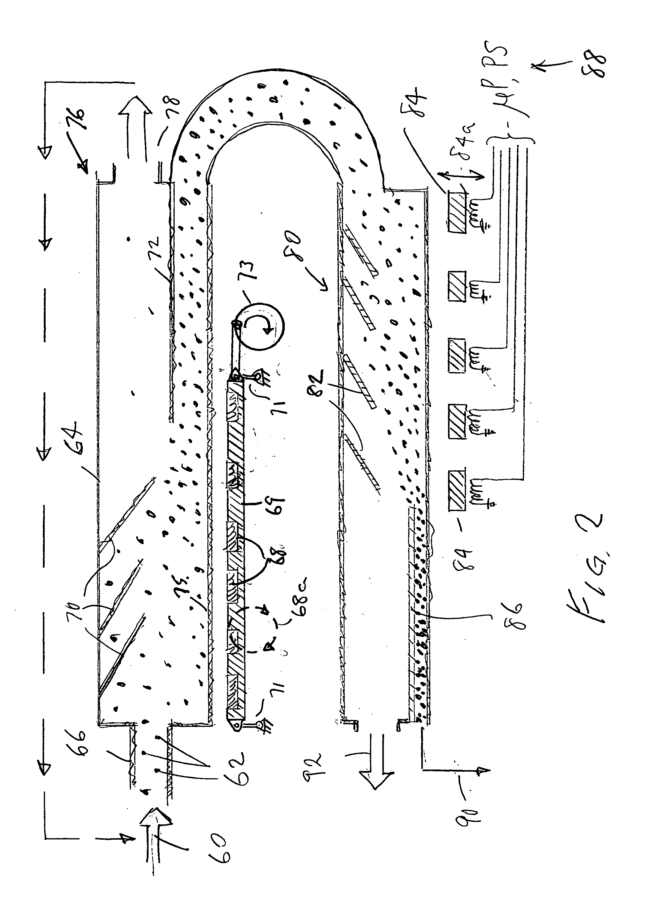
[0023] Finally, the location of the magnetite cleaning system can have an impact on solids loading in the final magnetic collector. A new and innovative approach is to locate the drum that collects magnetite for cleaning in front of the final collector. In this way, solids are removed for cleaning from the water that is about to exit through the final magnetic collector.

Problems solved by technology

It is recognized that this approach effectively removes large particles like grit and floatables, but does not effectively remove fine pollutant particles.

Method used


Image

  • Water treatment using magnetic and other field separation technologies
  • Water treatment using magnetic and other field separation technologies
  • Water treatment using magnetic and other field separation technologies

Examples


Embodiment Construction

[0032] As described above, according to a first important aspect of the invention, vortex separation is combined with magnetic separation, and both are performed in the same tank. That is, the magnetic particles and the flocculant are introduced, and flocculation takes place, in the same tank where vortex separation is performed. The combination of these process steps in a single piece of apparatus makes it possible to design an efficient system to remove fine particles from large quantities of water. Actual separation of the composite magnetic particles formed upon flocculation may require an additional apparatus. In an alternative embodiment, useful where settleable solids such as silt, floating debris, and fine particles may all be present, this apparatus can further comprise equipment for removing settleable and floating pollutants as well.

[0033] As noted, it is within the invention to refit certain preexisting equipment, e.g. existing vortex separators used for removing grit a...


PUM

PropertyMeasurementUnit
magneticaaaaaaaaaa
magnetic fieldaaaaaaaaaa
lengthaaaaaaaaaa

Abstract

Apparatus and methods for removal of pollutants from a stream of water, by binding the pollutant particles to magnetic seeding particles using a flocculating polymer, and then removing the composite magnetic particles from the water stream in a simple and efficient apparatus. The invention is applicable to many common water treatment applications but is especially important for high flow applications requiring efficiency and simplicity. Magnetic fields concentrate the composite magnetic particles in a stratified layer that is then continually separated from the moving stream of water. In another preferred embodiment, vortex separation is combined with magnetic separation to enhance magnetic seed material cleaning and to reduce the solids load on the final magnetic collector.

Description

CROSS-REFERENCE TO RELATED APPLICATION [0001] This application claims priority from Provisional Application Ser. No. 60 / 708,789 filed Aug. 17, 2005.FIELD OF THE INVENTION [0002] This invention relates to removing fine particles, including metal precipitates, organic solids, inorganic solids, clays, silts, oil and grease, and any other hard to remove fine solids from water. It is applicable to industrial wastewater, municipal wastewater, potable water, combined sewer overflow, storm water, process water, cooling water and any other waters that require clarification to remove fine particles. The invention relates to the use of magnetic separation technology where a fine magnetic seed material, preferably magnetite (a magnetic form of iron oxide), is added to water along with an organic flocculating polymer. The organic flocculating polymer binds the non-magnetic pollutant particles to the magnetic seed material, so that the composite particles can then be removed magnetically from the...

Claims


Application Information

Patent Timeline
Patent Type & Authority Applications(United States)
IPC IPC(8): C02F1/48
CPCC02F1/488B03C1/01B03C1/12B03C1/286B03C1/288B03C1/30
Inventor CORT, STEVEN L.
Owner CORT STEVEN L
Learn More