Fiber charging apparatus

a charging apparatus and fiber technology, applied in the direction of filament/thread forming, fibre treatment, manufacturing tools, etc., can solve the problems of physical interruption of process solution and/or solvent supply, insufficient voltage potential of the pack, and extremely difficult to meet the insulation requiremen

Active Publication Date: 2007-02-22
DUPONT SAFETY & CONSTR INC
View PDF15 Cites 37 Cited by
  • Summary
  • Abstract
  • Description
  • Claims
  • Application Information

AI Technical Summary

Benefits of technology

[0014] The term “fine polymer fibers” refers to substantially continuous polymeric fibers having average effective diameters of less than about 1 micrometer.
[0015] The term “corona discharge” means a self-sustaining, partial breakdown of a gas subjected to a highly divergent electric field such as that arising near the point in a point-plane electrode geometry. In such an arrangement, the electric field, Ep, at the corona point is considerab

Problems solved by technology

There are several disadvantages to the apparatus disclosed in PCT publication no.
Because the polymer solution is conductive, all of the equipment in contact with the polymer solution is brought to high voltage, and if the motor and gear box driving the polymer solution pump are not electrically isolated from the pump, a short circuit will be created which will reduce the voltage potential of the pack to a level insufficient to create the electric fields required to impart charge on the polymer solution.
Another disadvantage of the prior art electroblowing apparatus is that the process solution and/or solvent supply must be physically interrupted in order to isolate it from the high voltage of the process.
This insulation requirement is extremely difficult to fulfill as this includes large equipment such as spin packs, transfer lines, metering pumps, solution storage tanks, pumps, as well as control equipment and instrumentation such as pressure

Method used


Image

  • Fiber charging apparatus
  • Fiber charging apparatus
  • Fiber charging apparatus

Examples


example 1

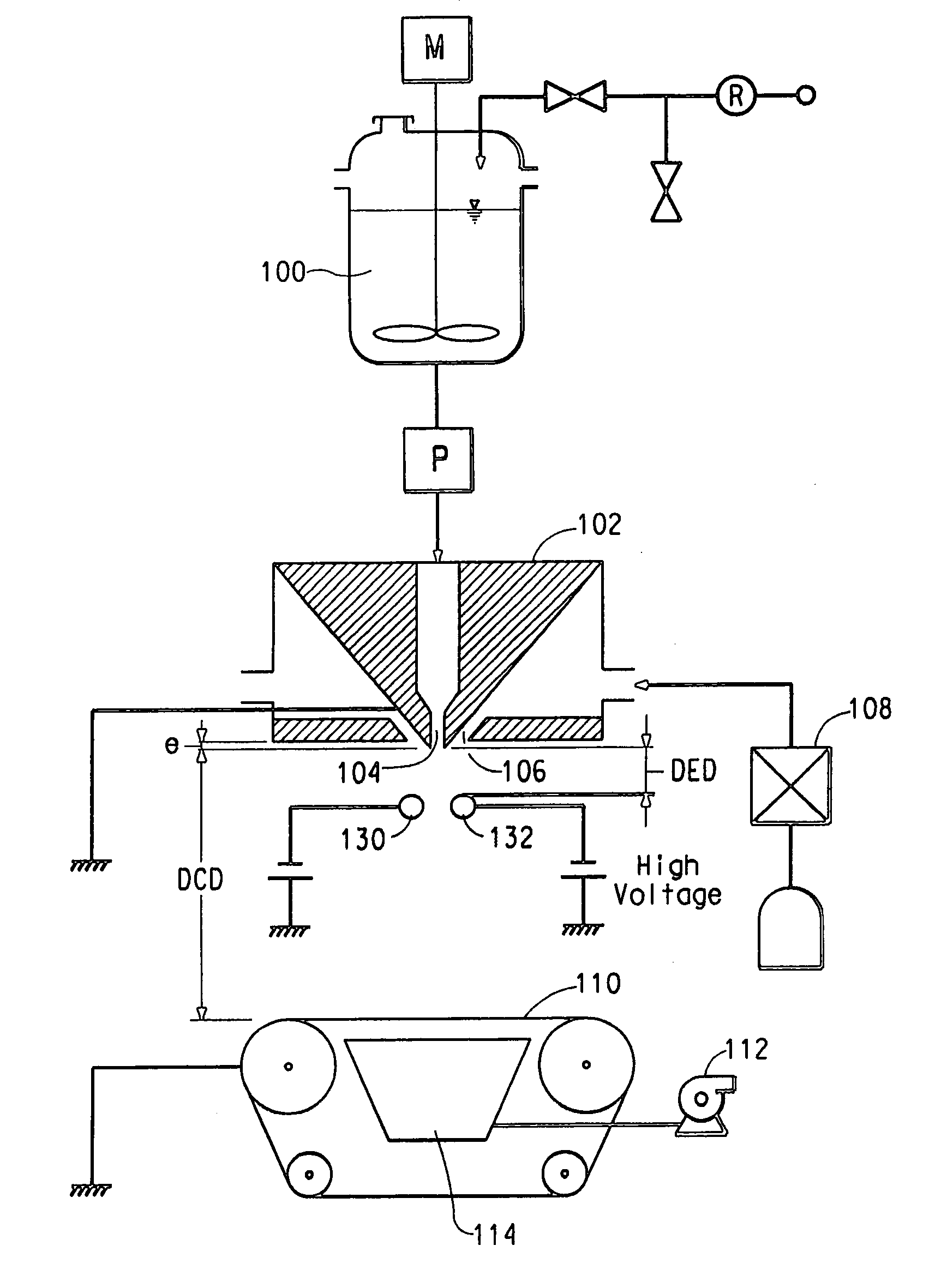
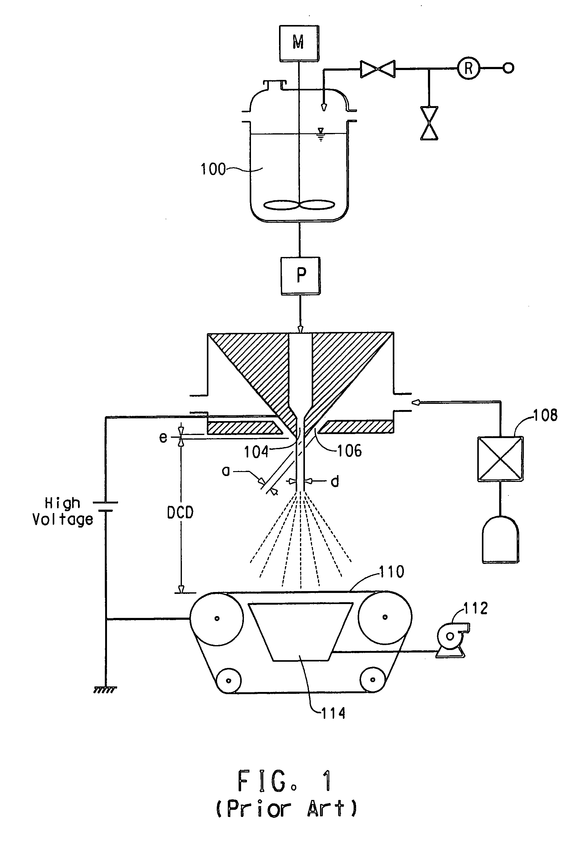
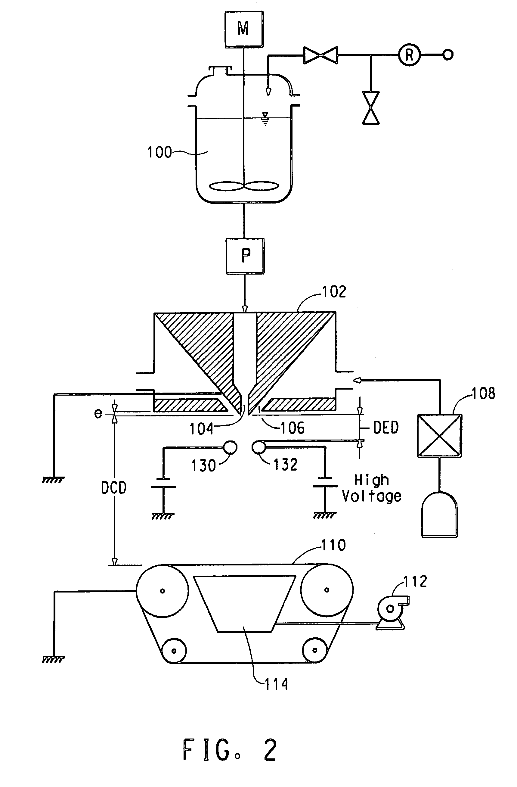
[0045] A polyvinyl alcohol (PVA), Elvano® 85-82, available from DuPont was dissolved in deionized water to make a 10% by weight PVA solution. The solution electrical conductivity was measured to be 493 micro-Siemens / cm using a VWR digital conductivity meter available from VWR Scientific Products (VWR International, Inc., West Chester, Pa.). The solution was spun in a single orifice electroblowing apparatus comprising a 22 gauge blunt syringe needle, in a concentric forwarding air jet. The needle tip protruded 2 mm below the conductive face of the spin pack body. The spin pack body and the spin orifice were electrically grounded through an ammeter, and the PVA solution was directed through a gap between an array of needles charged to a high voltage, which served as the point-electrode and a grounded, cylindrical target-electrode. Process conditions are set forth in the Table, below.

[0046] PVA fine fibers formed via this process were collected on a grounded conductive surface and exa...

example 2

[0047] A 7.5% by weight solution of polyethylene oxide (PEO), of viscosity average molecular weight (Mv) 300,000, obtained from Sigma—Aldrich, was dissolved in deionized water. Sodium chloride (NaCl) at a concentration of 0.1 wt % was added to the PEO solution to increase the solution electrical conductivity. Once the solution was thoroughly mixed, the electrical conductivity was measured to be approximately 1600 micro-Siemens / cm, with the same digital conductivity meter being used as in Example 1. This solution was spun through a single orifice electroblowing apparatus with a 20 gauge blunt needle. The process conditions for this run are listed in the Table, below. The charging method for this run is the same as described in Example 1, utilizing a needle array, which served as the point electrode and a grounded, cylindrical target electrode.

[0048] PEO fine fibers produced during this run were collected on a grounded conductive surface. The average diameters of these fine fibers we...

example 3

[0049] The PEO solution of Example 2 was spun through the single orifice electroblowing apparatus, however the point-electrode geometry was varied. Instead of an array of needles providing the charge, a single wire was used. The solution was directed through the gap between the single wire electrode and a grounded bar, and charged with high voltage. The grounded cylinder served as the target electrode. The conditions used in this run are listed in the Table, below.

[0050] The PEO fine fibers were collected on a conductive surface, which was grounded, and their average diameters were examined under a scanning electron microscope, and the average effective fiber diameter from the wire electrode system was also around 500 nm.

TABLEEx. 1Ex. 2Ex. 3Solution10 wt %7.5 wt % PEO / 0.17.5 wt %PVA / waterwt % NaCl / waterPEO / 0.1 wt %NaCl / waterSolution49316001600Conductivity(uS / cm)Capillary ID (mm)0.41 (22 G)0.6 (20 G)0.6 (20 G)Charging sourceNeedle arrayNeedle ArrayWire and BarSource polarityNegati...


PUM

PropertyMeasurementUnit
Lengthaaaaaaaaaa
Electrical conductoraaaaaaaaaa
Semiconductor propertiesaaaaaaaaaa

Abstract

A fiber spinning apparatus for charging a polymer-containing liquid stream, having at least one electrically charged, point-electrode positioned adjacent the intended path of said liquid stream and creating an ion flow by corona discharge to impart electrical charge to the polymer-containing liquid stream.

Description

FIELD OF THE INVENTION [0001] The present invention relates to an apparatus for forming a fibrous web wherein a polymer-containing liquid stream is spun through a spinning nozzle into an electric field of sufficient strength to impart electrical charge on the stream to form fibers, and optionally wherein a forwarding gas stream aids in transporting the liquid stream away from the spinning nozzle. BACKGROUND OF THE INVENTION [0002] PCT publication no. WO 03 / 080905A discloses an electroblowing apparatus and method for producing a nanofiber web. The method comprises feeding a polymer solution to a spinning nozzle to which a high voltage is applied while compressed gas is used to envelop the polymer solution in a forwarding gas stream as it exits the spinning nozzle, and collecting the resulting nanofiber web on a grounded suction collector. [0003] There are several disadvantages to the apparatus disclosed in PCT publication no. WO 03 / 080905A, particularly if the process is carried out ...

Claims


Application Information

Patent Timeline
IPC IPC(8): B29C47/00D04H1/728
CPCD01D5/0061D04H1/728D04H1/56D01D5/0069D01D5/00D01D5/098
Inventor ARMANTROUT, JACK EUGENEJOHNSON, BENJAMIN SCOTTRUDE, COLBEY ABRAHAMBRYNER, MICHAEL ALLEN
Owner DUPONT SAFETY & CONSTR INC
Why Eureka
Try Eureka