
DC brushless fan motor driving circuit

a brushless fan and driving circuit technology, applied in the direction of dc motor speed/torque control, electric motor speed/torque regulation, control system, etc., can solve the problem of large change rate of coil current, electromagnetic noise of fan motor driven by forgoing controlling signals, and limited frequency of trapezoidal wave signals in a specific range. problem, to achieve the effect of reducing electromagnetic nois

Inactive Publication Date: 2007-03-01
ADDA
View PDF2 Cites 24 Cited by
  • Summary
  • Abstract
  • Description
  • Claims
  • Application Information

AI Technical Summary

Benefits of technology

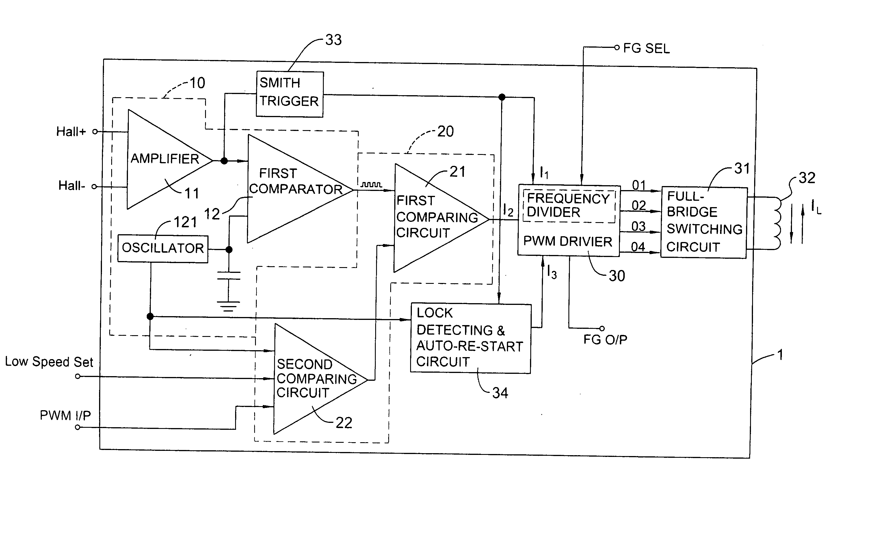
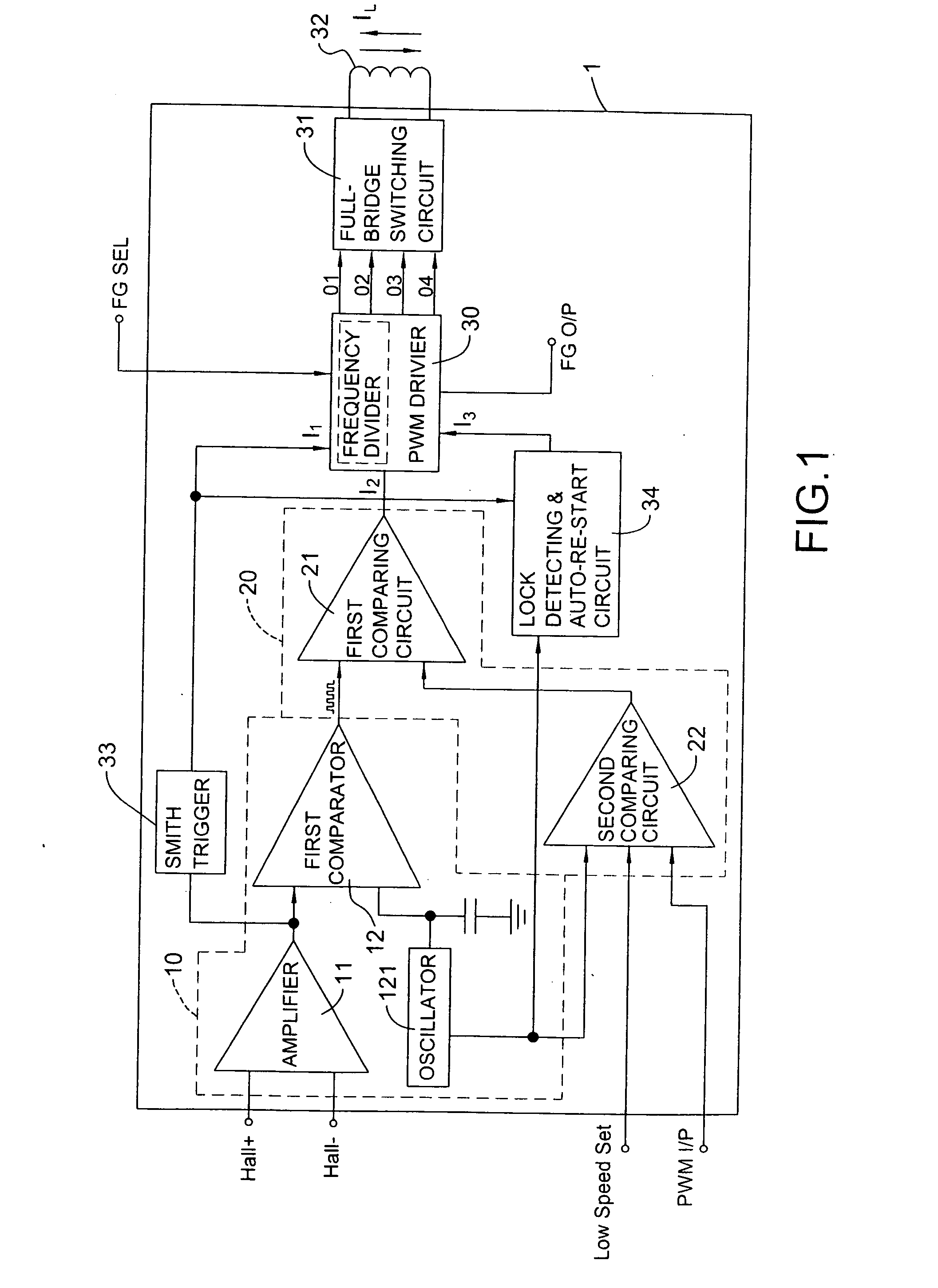
"The present invention provides a DC brushless fan motor driving circuit that reduces electromagnetic noise when the fan motor is driven. The circuit includes a Hall PWM signal generator, a speed signal generator, a PWM driver, and a full-bridge switching circuit. The Hall PWM signal generator obtains a Hall sine wave signal from an external Hall sensor and converts it to a varied Hall PWM signal. The speed signal generator sets the speed of the fan motor and receives the varied Hall PWM signal to compare it with a present speed setting signal. The PWM driver outputs a SPWM signal to the full-bridge switching circuit, which then forms a coil current close to a sine wave signal to decrease the electromagnetic noise. The technical effect of this invention is to reduce the noise generated by the fan motor and improve its performance."

Problems solved by technology

However, each coil current (IL1˜IL3) has a serious ripper phenomenon and the rate of change of the coil current is large.
Therefore, the fan motor driven by the forgoing controlling signals will be electromagnetically noisy.
Although the trapezoidal wave signal slightly reduces the electromagnetic noise, the frequency of the trapezoidal wave signal is limited in a specific range.
Therefore, the motor driving circuit with the trapezoidal wave signal has higher power consumption.

Method used


Image

  • DC brushless fan motor driving circuit
  • DC brushless fan motor driving circuit
  • DC brushless fan motor driving circuit

Examples


Embodiment Construction

[0027] With reference to FIG. 1, a driving circuit in accordance with the present invention for DC brushless fan motor with a single coil (32) has a Hall pulse width modulation (PWM) signal generator (10), a speed signal generator (20), a PWM driver (30) and a full bridge switching circuit unit (31), which can be integrated into one integrated circuit (IC) element (1).

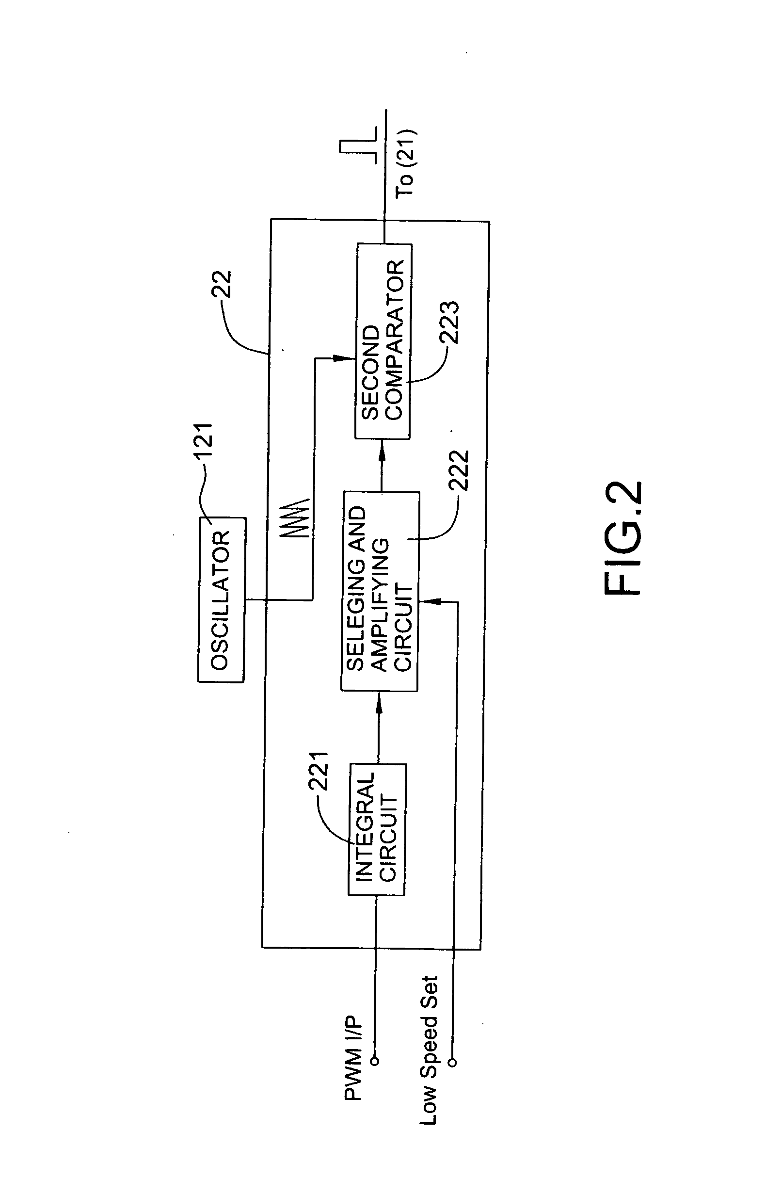
[0028] The Hall PWM signal generator (10) has an amplifier (11), a first comparator (12) and an oscillator (121). The amplifier (11) is connected to an external Hall sensor (not shown) that outputs a Hall sine wave signal and amplifies the Hall sine wave signal. The first comparator (12) has two inputs and one output. One input is connected to the amplifier (11), and the other one is connected to the oscillator (121) that outputs an oscillating signal. Therefore, with further reference to FIG. 3A, the first comparator (12) compares the Hall sine wave signal (SH) through the amplifier (11) to the oscillating signal (OS...


PUM


Abstract

A DC brushless fan motor driving circuit has a Hall PWM signal generator, a speed signal generator, a PWM driver and a full-bridge switching circuit. The Hall PWM signal generator obtains a Hall sine wave signal from an external Hall sensor and converts the Hall sine wave signal to a varied Hall PWM signal. The speed signal generator is connected to an external PWM input signal to set speed of a fan motor and a low speed voltage to determine a present speed setting signal. The speed signal generator further obtains the varied Hall PWM signal to compare the present speed setting signal to generate a SPWM signal to the PWM driver. The PWM driver outputs a SPWM signal to the full-bridge switching circuit and then coil current is formed close to a sine wave signal to decrease the electromagnetic noise.

Description

BACKGROUND OF THE INVENTION [0001] 1. Field of the Invention [0002] The present invention relates to a driving circuit for a DC brushless fan motor, and more particularly to a DC brushless fan motor driving circuit having low electromagnetic noise. [0003] 2. Description of Related Art [0004] Two types of driving circuit exist to drive a DC brushless fan motor that has a single coil (52). One type is a single-phase full-wave motor driving circuit, and the other one type is a two-phase half-wave motor driving circuit. Each motor driving circuit uses a driver element to drive the fan motor, and the output driving signal of the driver is a form of pulse width modulation (PWM). [0005] With reference to FIG. 4, one DC brushless fan motor driving circuit has a PWM driver (50), a Smith trigger (53), a Hall sensor (not shown), a lock detecting and auto-re-start circuit unit (54), an oscillator (501) and a full-bridge switching circuit unit (51). [0006] The PWM driver (50) has a Hall signal i...

Claims


Application Information

Patent Timeline
Patent Type & Authority Applications(United States)
IPC IPC(8): H02P5/06
CPCH02P2209/07H02P6/06
Inventor HSIEH, HSIN-MAO
Owner ADDA
Learn More