Optical transmitter-receiver, optical transmitter-receiver module, and optical communication device

a technology of optical transmitter and optical communication device, applied in the direction of instruments, photometry using electric radiation detectors, optical elements, etc., can solve the problems of large size of optical coupling portion, difficult to reduce the size and/or integrate constructive elements, and degrading the light receiving sensitivity of light receiving elements, etc., to reduce cross-talk, reduce the size, and reduce the effect of device siz

Inactive Publication Date: 2007-03-08
FUJIFILM BUSINESS INNOVATION CORP
View PDF8 Cites 29 Cited by
  • Summary
  • Abstract
  • Description
  • Claims
  • Application Information

AI Technical Summary

Benefits of technology

[0026] According to the above optical communication device, it is possible to reduce cross-talk between the transmitting side and the receiving side since the circuit board exists between the terminals related to the light emitting element and the terminals related to the light receiving element. Further, downsizing of the device can be realized by mou

Problems solved by technology

However, when a light emitting element, which is driven with high speed large current, is arranged in the vicinity of a light receiving element, which receives very small light, and/or the amplifying IC, which amplifies very small current, electrical cross-talk occurs by electromagnetic noise due to current driving the light emitting element, resulting in degradation of light receiving sensitivity of the light receiving element.
However, in the related art disclosed in JP-A-5-100132 and JP-A-2005-3860, in which the light emitting element and the light receiving element are positioned in mutually remote locations, it is difficult to reduce the size and/or to integrate the constructive elements.
Therefore, when an interacti

Method used


Image

  • Optical transmitter-receiver, optical transmitter-receiver module, and optical communication device
  • Optical transmitter-receiver, optical transmitter-receiver module, and optical communication device
  • Optical transmitter-receiver, optical transmitter-receiver module, and optical communication device

Examples


first embodiment

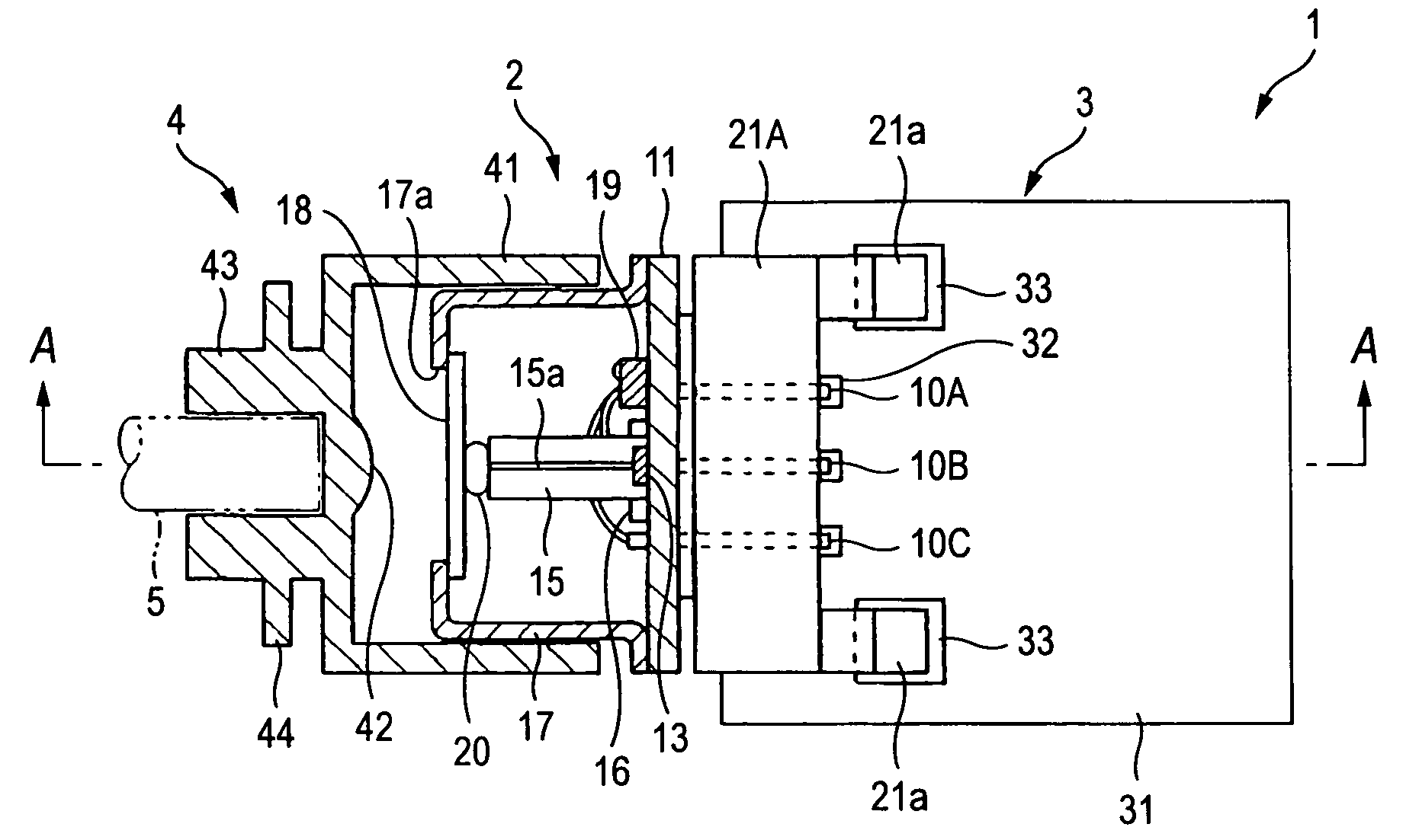
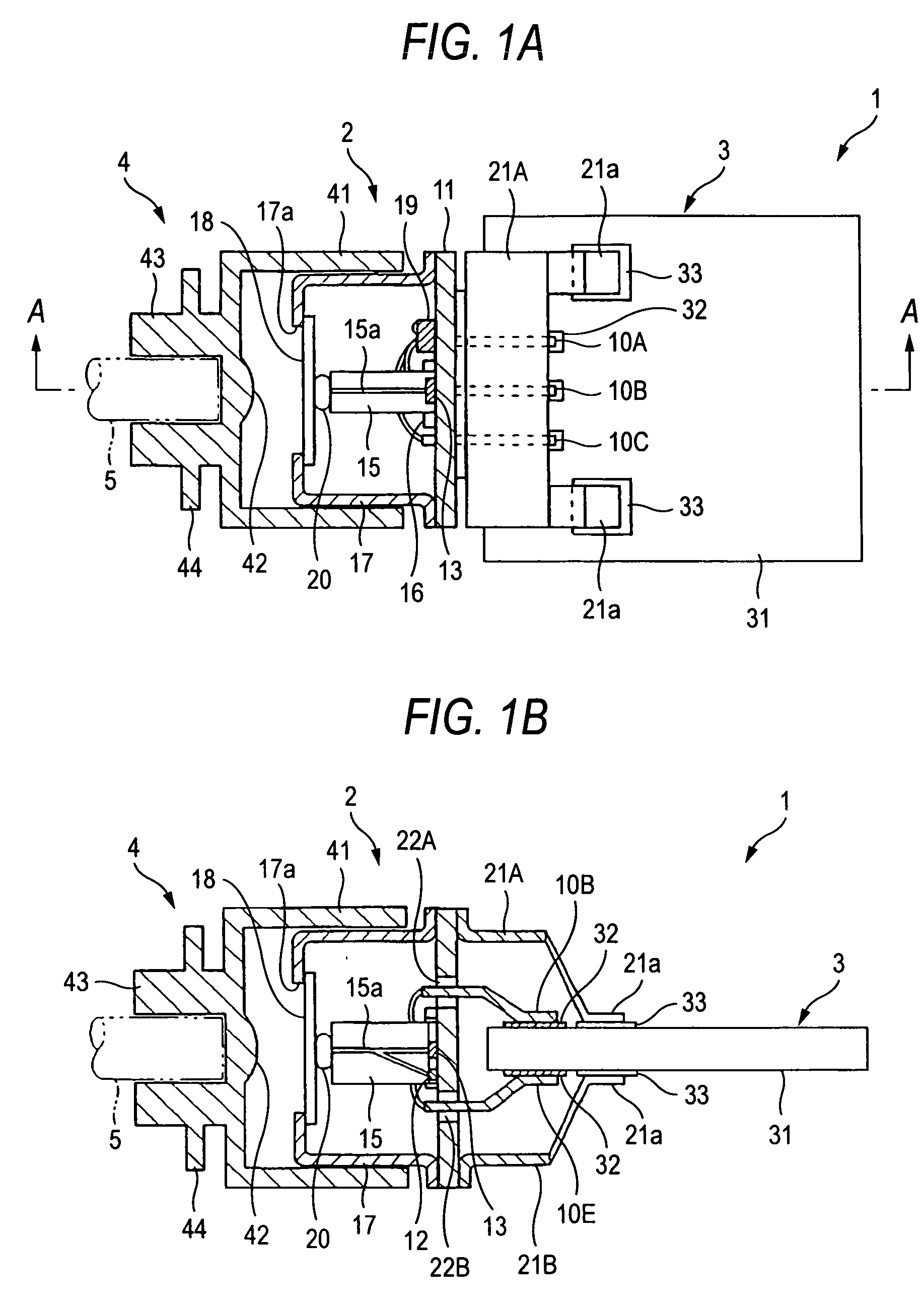
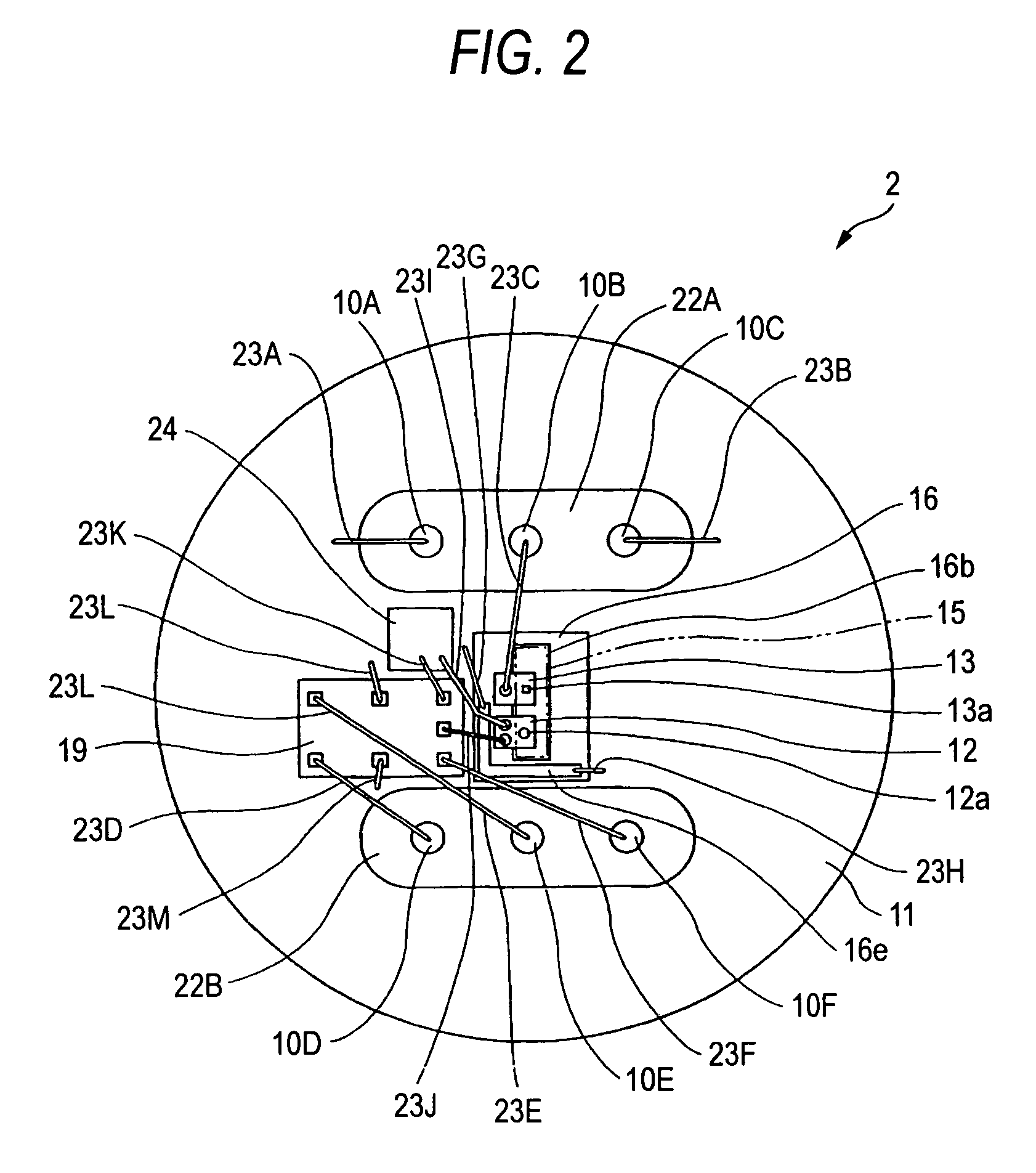
[0046]FIGS. 1A and 1B show an optical transmitter-receiver according to a first embodiment of the present invention, in which FIG. 1A is a plan view thereof and FIG. 1B is a cross sectional view taken along a line A-A in FIG. 1A. FIG. 2 shows a detailed construction of the optical module shown in FIG. 1. Incidentally, a cross section of the optical module is shown in FIG. 1A. FIG. 2 shows mounting parts on a stem and an optical waveguide is shown by imaginary chain lines.

[0047] The optical transmitter-receiver 1 includes a CAN package type optical module 2 to which an optical fiber 5 as an optical transmission medium is connected through a coupler member 4, a circuit board 3 mounting the optical module 2 thereon and transmitting / receiving an electric signal with respect to the optical module 2 and shield members 21A and 21B provided on the circuit board 3, for shielding electrode pins 10 (10A to 10F) as a wiring portion of the optical module 2.

[0048] The optical module 2 includes ...

second embodiment

[0082]FIGS. 4A and 4B show an optical transmitter-receiver according to the second embodiment of the present invention, in which FIG. 4A is a bottom view thereof and FIG. 4B is a cross section taken along a line B-B in FIG. 4A.

[0083] The second embodiment differs from the first embodiment in that the shield member 21B on the receiving side is replaced by a shield member 21C having lower rigidity, the transmitting side shield member 21A is removed, grounding electrode pins 25A and 25B are provided in the vicinity of the opposite sides of the receiving side electrode pins 10D to 10F and the grounding electrode pins 25A and 25B are connected to the solder pads 33. The other configurations are similar to those of the first embodiment.

[0084] The shield member 21C may be formed from, for example, a copper foil having low rigidity and covers the electrode pins 10D to 10F. Connecting pieces 21a to be connected to the solder pads 33 extend from both sides of the shield member 21C.

[0085] S...

third embodiment

[0089]FIGS. 5A and 5B show an optical transmitter-receiver according to the third embodiment of the present invention, in which FIG. 5A is a plan view thereof and FIG. 5B is a side view thereof. FIGS. 6A and 6B are development of a flexible circuit board on which the optical module is mounted, in which FIG. 6A is a plan view and FIG. 6B is a cross section taken along a line C-C in FIG. 6A.

[0090] The optical transmitter-receiver 1 according to the third embodiment includes the optical module 2 and the circuit board 3 of the first embodiment and a flexible circuit board 6 connecting the optical module 2 to the circuit board 3. The construction of the optical module 2 is similar to the first embodiment shown in FIGS. 1A, 1B and 2. In the third embodiment, however, the electrode pins 10A to 10F are shortened compared with the first embodiment since these are mounted on the thin flexible circuit board 6.

[0091] As shown in FIG. 5B, the circuit board 3 has a connector 34 for connecting t...


PUM


Abstract

An optical transmitter-receiver includes: an optical module including a metal package housing at least a light receiving element and a light emitting element; a circuit board for transmitting/receiving an electric signal with respect to the optical module; a first wiring for connecting a side of the light receiving element to the circuit board; a second wiring for connecting a side of the light emitting element to the circuit board; and a shield member for shielding at least the first wiring.

Description

BACKGROUND OF THE INVENTION [0001] 1. Field of the Invention [0002] The present invention relates to an optical transmitter-receiver for performing an interactive optical communication through an optical transmission medium by using an optical transmission-receiving module having a light emitting element and a light receiving element. [0003] 2. Description of the Related Art [0004] The one-core interactive optical communication system using a single optical fiber has been developed. In such one-core interactive optical communication system, an optical transmitter-receiver having optical elements such as a light emitting element and a light receiving element, an optical waveguide for optically coupling the optical elements with an optical fiber and an amplifying IC, etc., is used. In order to popularize the one-core interactive optical communication system, the development of low cost optical transmitter-receiver is important and, for this reason, it is necessary to integrate the opt...

Claims


Application Information

Patent Timeline
IPC IPC(8): H01J40/14G01J1/44
CPCG02B6/4204G02B6/421H01L2924/3025H01L2924/30107H01L2924/3011H01L2224/48137H05K2201/10446G02B6/4246G02B6/4277G02B6/4292H05K1/0243H05K3/3405H05K3/3421H05K2201/10121H05K2201/10371H01L2924/00
Inventor SAKAI, KAZUHIROOHTANI, OSAMUUENO, OSAMU
Owner FUJIFILM BUSINESS INNOVATION CORP
Why Eureka
Try Eureka