Vertical cavity surface emitting laser including trench and proton implant isolation

a laser and vertical cavity technology, applied in the field of lasers, can solve the problems of reducing affecting the efficiency of the vcsel, so as to increase the vcsel layer size and increase the absorption

Active Publication Date: 2007-03-08
II VI DELAWARE INC
View PDF4 Cites 14 Cited by
  • Summary
  • Abstract
  • Description
  • Claims
  • Application Information

AI Technical Summary

Benefits of technology

[0018] While the current designs have been acceptable for shorter wavelength VCSELs such as VCSELs emitting 850 nanometer (nm) wavelength light, longer wavelength VCSELs have been more difficult to achieve. For example, in long wavelength VCSELs, absorption coefficients are larger. Additionally, due to the longer wavelengths and resulting increase in VCSEL layer size, increased absorption occurs. Specifically, VCSELs have layers that are optimized based on the wavelength at which the VCSEL is designed to lase. A quarter wavelength section in a 1310 nm VCSEL is longer than a quarter wavelength section in an 850 nm VCSEL. Thus, a 1310 nm VCSEL has more material where free carriers can be absorbed than an 850 nm VCSEL.

Problems solved by technology

Doping the mirrors results in various difficulties in lasers designed to produce longer wavelengths.
The higher mirror loss also lowers the efficiency of the VCSEL.
This increases the internal heating and limits the amount of power that a VCSEL can output.
Further, the restriction on doping level caused by absorption in the top mirror decreases the electrical conductivity of the VCSEL which causes resistive heating in the VCSEL which limits power output, and degrades reliability.
Additionally, ramps of material composition at the boundaries between layers in the mirrors degrade thermal impedance and reflectivity.
If the VCSEL is not able to conduct heat away from the active region, the operating temperature of the VCSEL may rise.
If the mirror layers have a degraded reflectivity, additional layers may need to be used resulting in increased impedance and further increased heating of the VCSEL.
Excessive heating can damage the VCSEL or shorten the useful life of the VCSEL or degrade its performance.
In summary, various issues relate to VCSEL technologies, including free carrier absorption, series resistance, reliability, manufacturability, thermal resistance, polarization stability, single mode operation, optical isolation from external reflections and high temperature performance.
While the current designs have been acceptable for shorter wavelength VCSELs such as VCSELs emitting 850 nanometer (nm) wavelength light, longer wavelength VCSELs have been more difficult to achieve.
However, due to the thermal and optical characteristics and other difficulties described above of currently designed VCSELs, 1310 nm VCSELs have not currently been feasible.

Method used


Image

  • Vertical cavity surface emitting laser including trench and proton implant isolation
  • Vertical cavity surface emitting laser including trench and proton implant isolation
  • Vertical cavity surface emitting laser including trench and proton implant isolation

Examples


Embodiment Construction

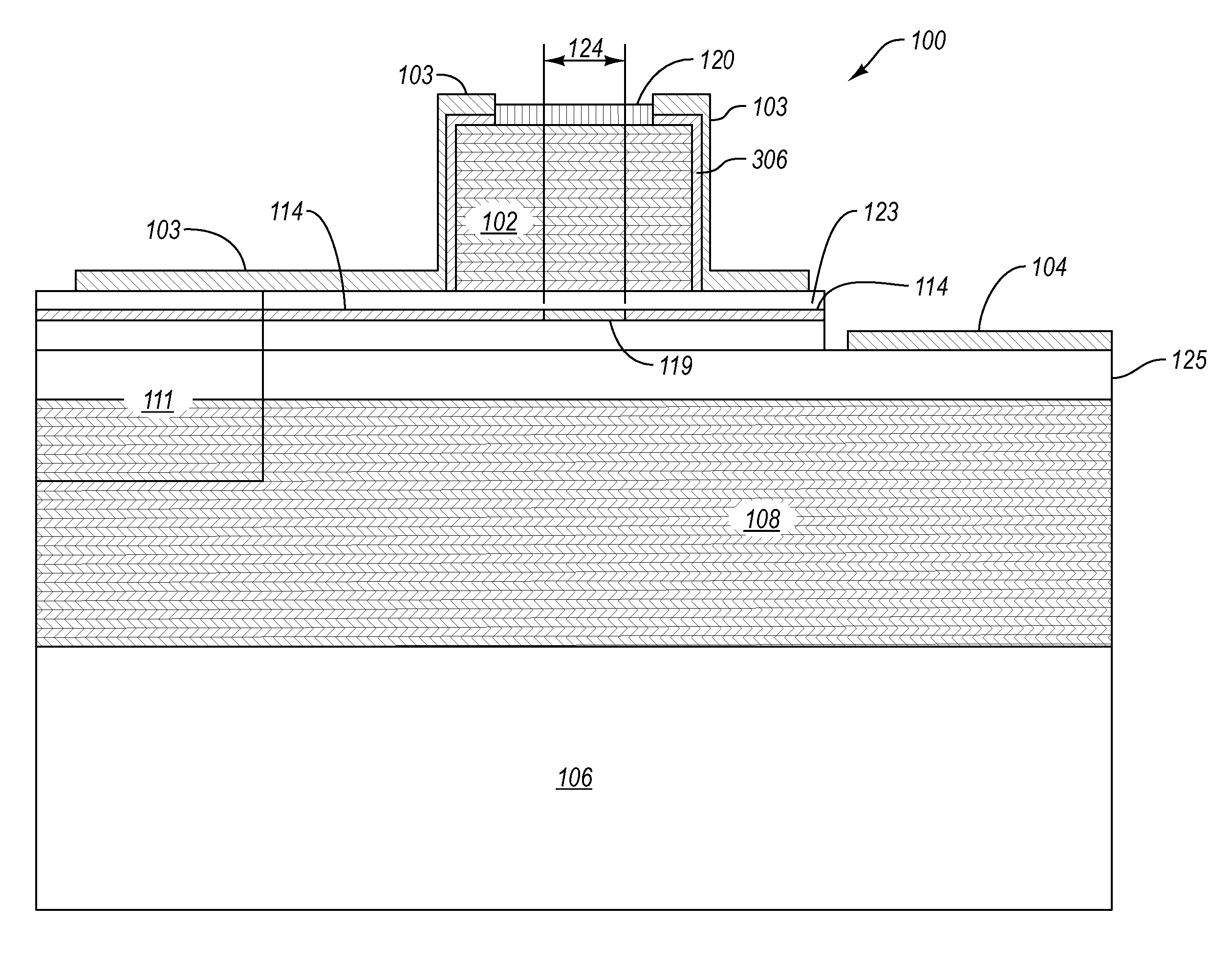
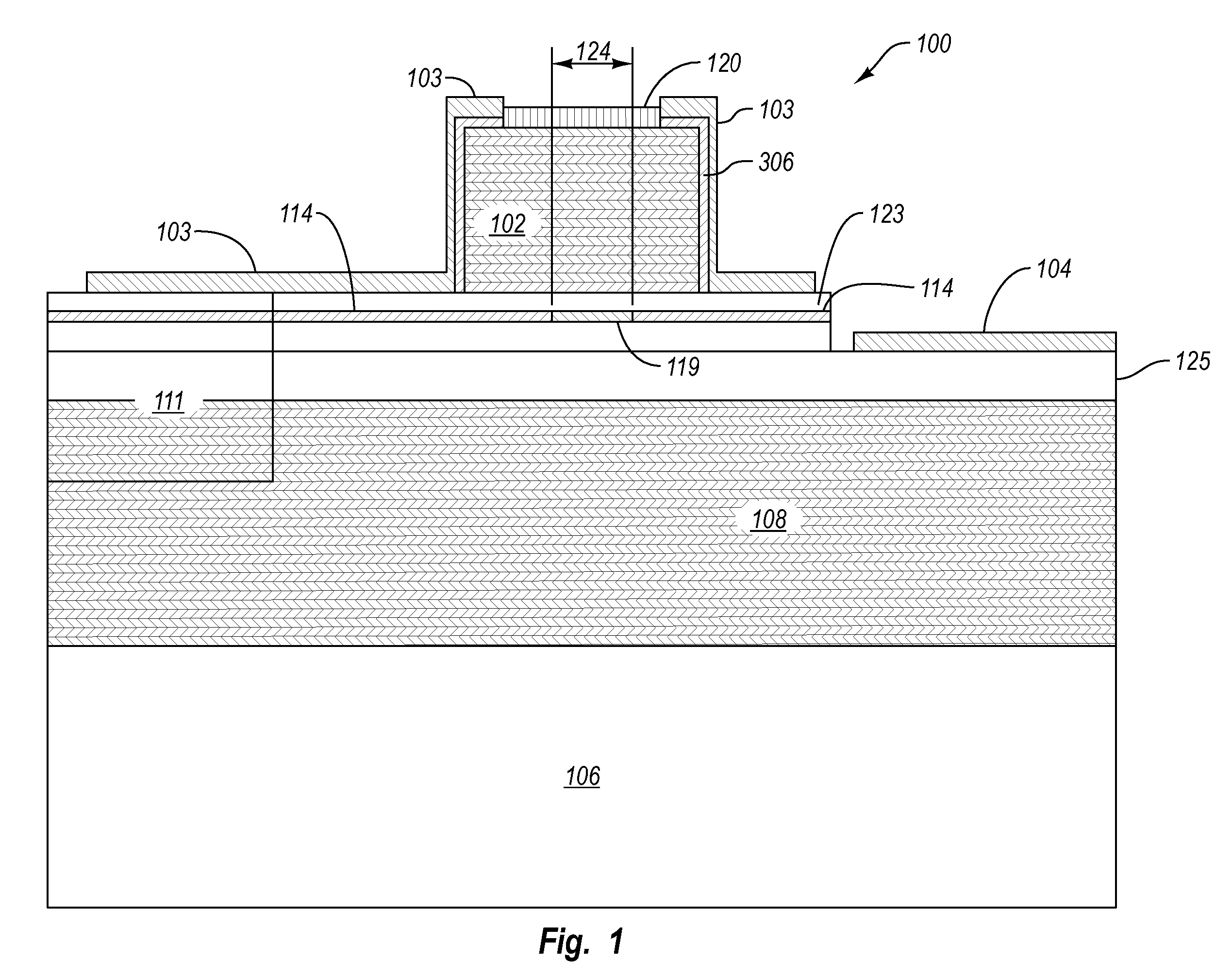
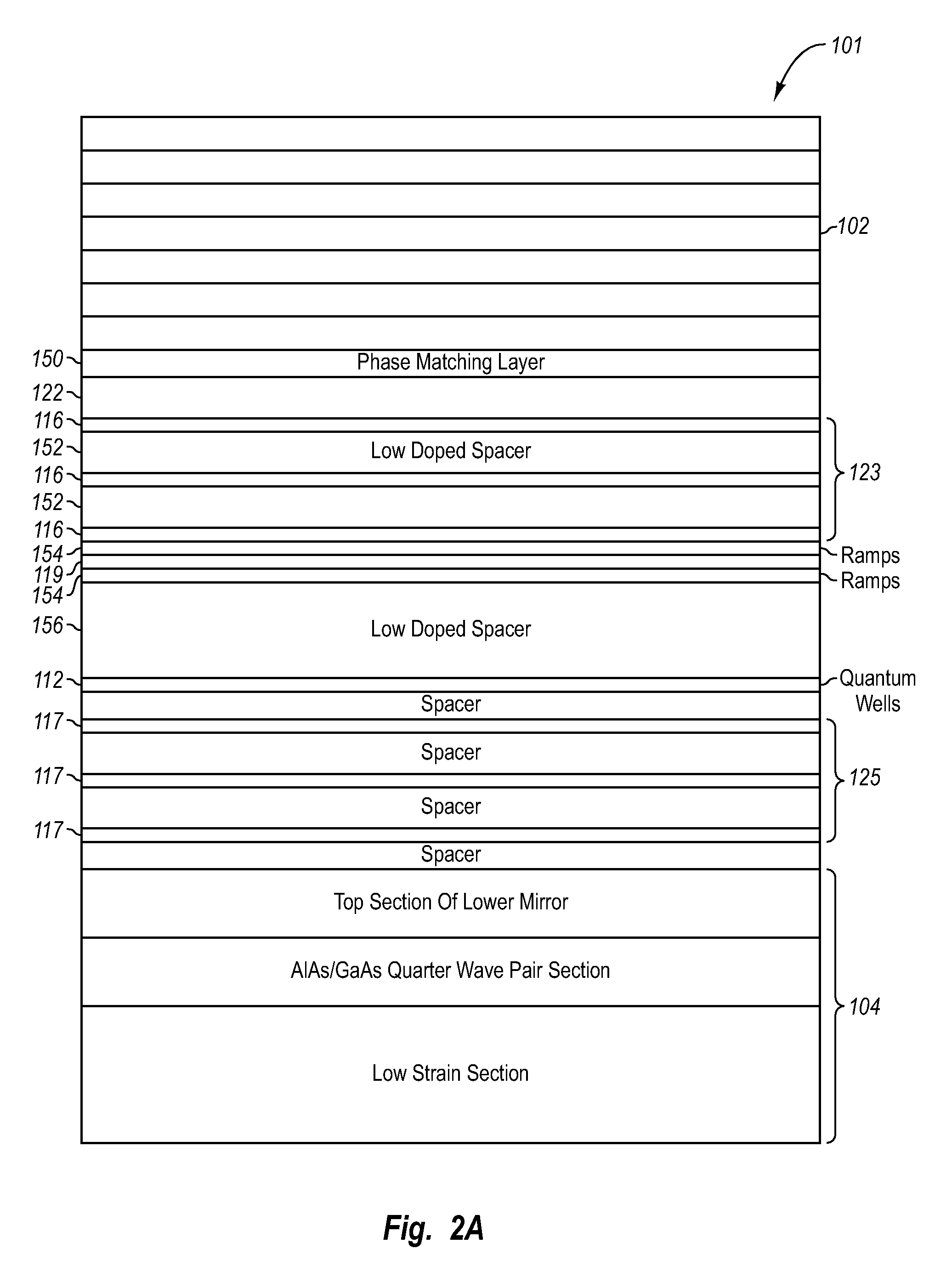
[0035] To address various problems in long wavelength VCSELS, embodiments described herein are optimized in one or more areas. For example, embodiments may incorporate minimized distances, periodic doping where carriers are placed predominately at the nulls of the optical electric field, minimized low mobility materials, and / or ramps in material compositions that are long enough to use low doping when they are not at nulls and thin higher doped portions when they are at or near nulls.

[0036] One embodiment improves performance of VCSELs at higher wavelengths by reducing or eliminating doping in the mirrors to minimize free carrier absorption and trap related absorption. Dual intracavity contacts can be connected to the active region via conduction layers to provide current to the active region for producing photons. Other layers of the VCSEL structure also use a method of periodic doping where dopants are more heavily concentrated at locations where the electrical field will be at a...


PUM


Abstract

A VCSEL with nearly planar intracavity contact. A bottom DBR mirror is formed on a substrate. A first conduction layer region is formed on the bottom DBR mirror. An active layer, including quantum wells, is on the first conduction layer region. A trench is formed into the active layer region. The trench is formed in a wagon wheel configuration with spokes providing mechanical support for the active layer region. The trench is etched approximately to the first conduction layer region. Proton implants are provided in the wagon wheel and configured to render the spokes of the wagon wheel insulating. A nearly planar electrical contact is formed as an intracavity contact for connecting the bottom of the active region to a power supply. The nearly planar electrical contact is formed in and about the trench.

Description

CROSS-REFERENCE TO RELATED APPLICATIONS [0001] This application is a continuation of U.S. Utility application Ser. No. 11 / 224,615 filed Sep. 12, 2005 titled Vertical Cavity Surface Emitting Laser Having Multiple Top-Side Contacts, which is a continuation in part of U.S. Utility application Ser. No. 11 / 222,433 titled Vertical Cavity Surface Emitting Laser with Undoped Top Mirror filed Sep. 8, 2005, which claims priority to U.S. Provisional Application No. 60 / 615,413, titled Vertical Cavity Surface Emitting Laser with Undoped Top Mirror filed Oct. 1, 2004, which are incorporated herein by reference in their entireties.BACKGROUND OF THE INVENTION [0002] 1. The Field of the Invention [0003] The invention generally relates to lasers. More specifically, the invention relates to Vertical Cavity Surface Emitting Lasers (VCSELs). [0004] 2. Description of the Related Art [0005] Lasers are commonly used in many modern components. One use that has recently become more common is the use of laser...

Claims


Application Information

Patent Timeline
Patent Type & Authority Applications(United States)
IPC IPC(8): H01S5/00
CPCH01S5/0425H01S5/18308H01S5/18311H01S5/3095H01S5/18341H01S5/18358H01S5/305H01S5/1833H01S5/04257
Inventor JOHNSON, RALPH H.PENNER, R. SCOTTBIARD, JAMES ROBERT
Owner II VI DELAWARE INC
Why Eureka
Try Eureka