
Complex-coupled distributed feedback semiconductor laser

a distributed feedback and semiconductor laser technology, applied in lasers, lasers, optical resonator shape and construction, etc., can solve the problems of poor single-mode operation, failure to meet the requirements of stable single-mode operation, and failure to meet the requirements of high single-mode yield and high output power

Active Publication Date: 2007-03-08
APPLIED OPTOELECTRONICS
View PDF7 Cites 5 Cited by
  • Summary
  • Abstract
  • Description
  • Claims
  • Application Information

AI Technical Summary

Benefits of technology

[0010] It is an object of the present invention to provide a complex-coupled DFB laser comprising an active QW grating, which complex-coupling coefficient is not affected by the variation of grating etching depth, and which has asymmetric laser output powers from AR coated laser facets with eliminating the effect of random facet grating phase.
[0018] According to another aspect of the present invention, there is provided a complex-coupled distributed feedback (DFB) laser device, comprising a semiconductor layer structure described as in the first embodiment, the laser cavity being composed of two cavity sections having different Bragg wavelengths. The portion of the laser cavity that is adjacent to the front facet of the cavity is referred to as the “front” cavity section, and the remaining portion of the cavity is referred to as the “back” cavity section. The front and back facets are AR coated, eliminating the random effect of facet grating phase.

Problems solved by technology

Some of the existing semiconductor lasers, for example, InGaAsP DFB lasers can meet requirements for the light sources for optical communication systems, but fail to satisfy requirements for stable single-mode operation which is insensitive to ambient temperature change (uncooled operation) and insensitive to external optical feedback (isolator-less operation), as well as meeting the requirements of high single-mode yield and high output power.
Conventional index-coupled DFB lasers employing an index corrugation have an inherent problem in existence of two longitudinal modes with an equal threshold gain which results in poor single mode operation as shown in the article by Kogelnik and C. V. Shank, “Coupled-mode theory of distributed feedback lasers”, Journal of Applied Physics, vol.
The yield, however, is relatively low due to the random variations of facet grating phase introduced by cleaving.
Although this type of DFB laser with perfect AR coatings has, in principle, 100% yield, the yield deterioration due to reflectivities of a few percent is rapid.
Furthermore, the output power from the front facet is relatively low due to a symmetric nature in which the same amount of power is emitted and wasted from the back facet.
However, this type of laser has relatively low external quantum efficiency due to too large index coupling induced by periodically etched QW's, losses in the groove regions where there is little gain medium.
In the complex-coupled DFB lasers with periodically etched MQW's, described above, however, there are still fundamental problems such as (1) variations of the complex coupling coefficient due to variations of grating etching depth, and (2) laser performance variations due to random variations of facet grating phase.

Method used


Image

  • Complex-coupled distributed feedback semiconductor laser
  • Complex-coupled distributed feedback semiconductor laser
  • Complex-coupled distributed feedback semiconductor laser

Examples


first embodiment

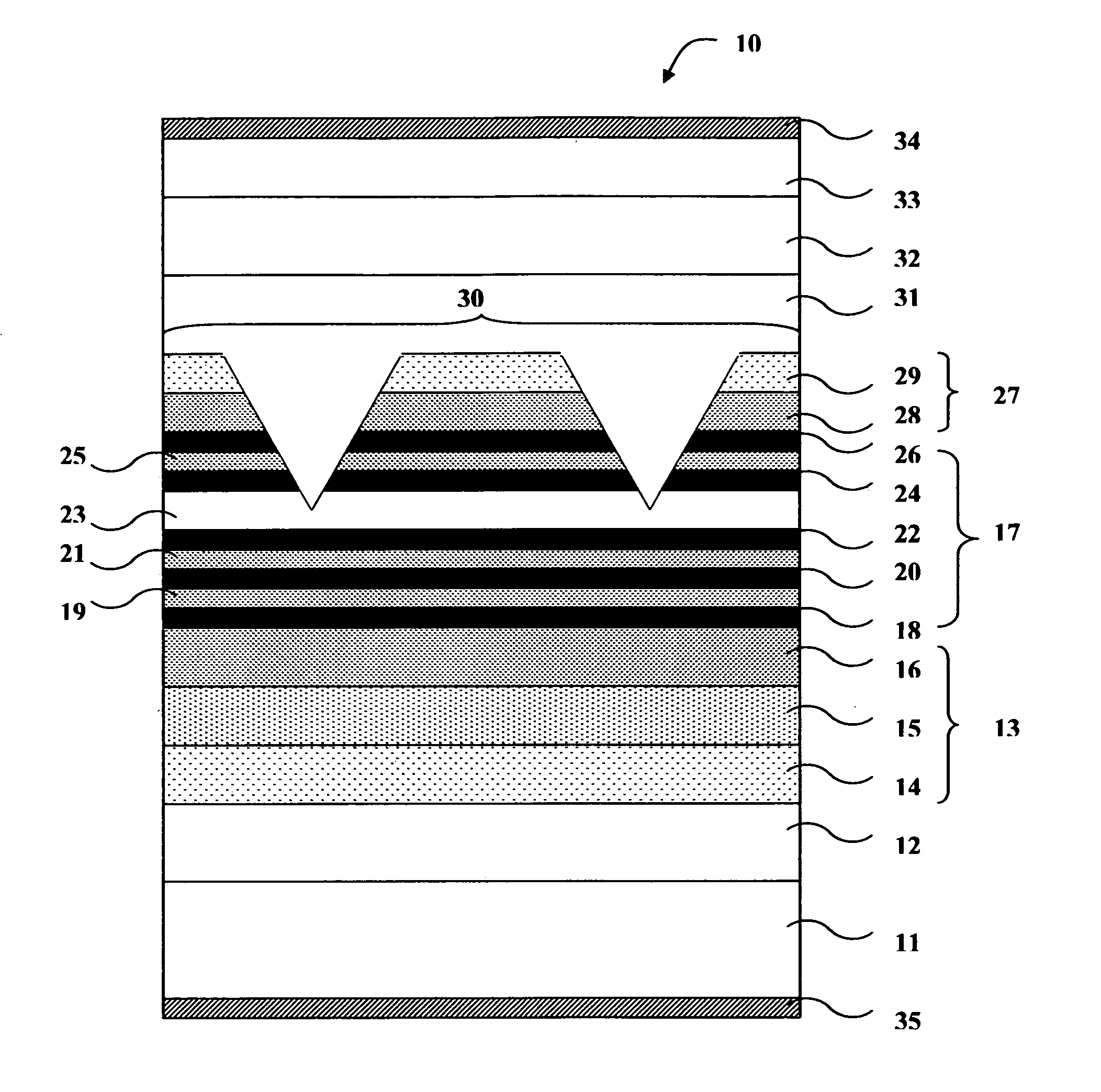
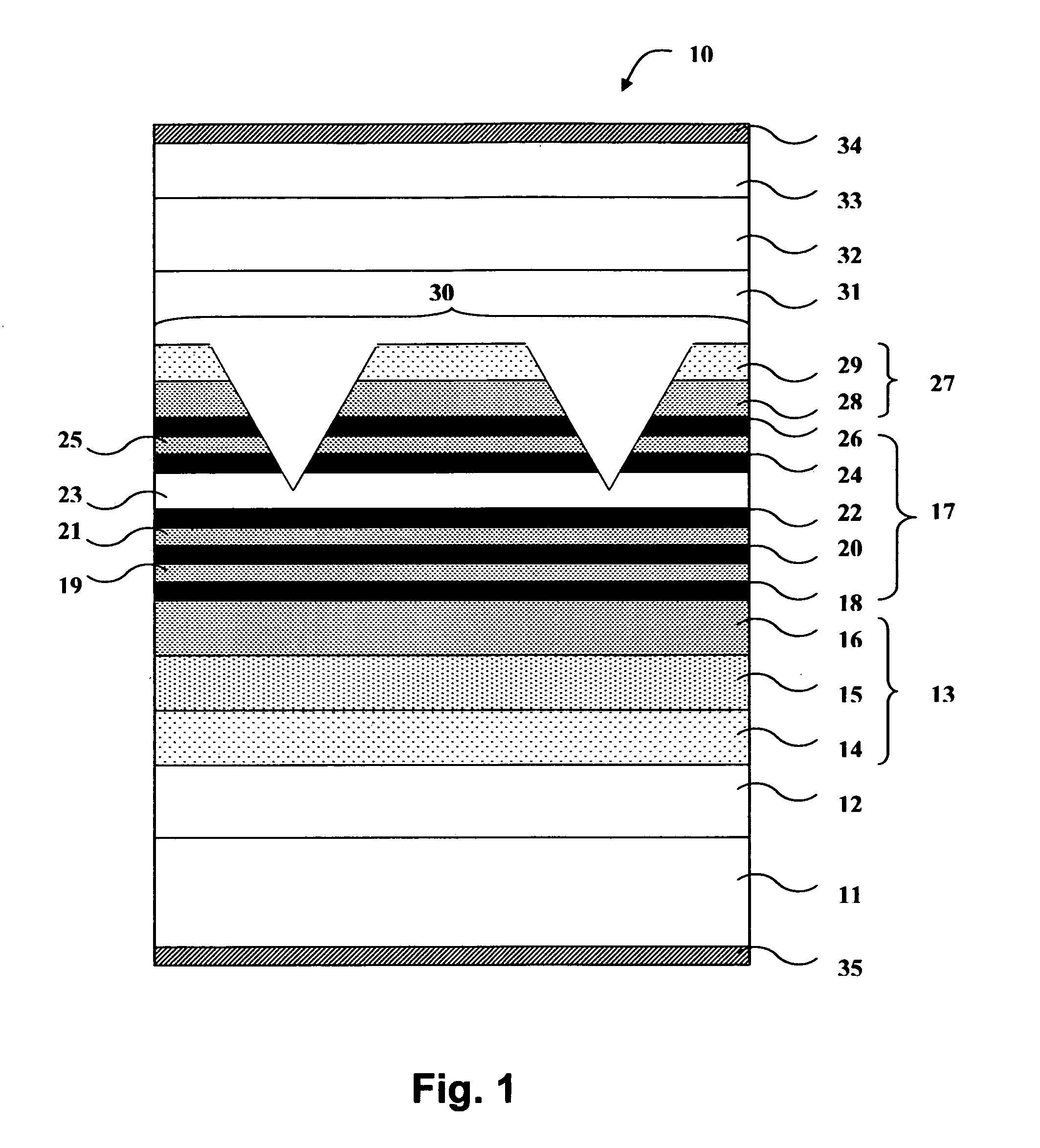
[0029] A schematic cross section through a complex-coupled DFB laser device 10 according to the present invention is shown in FIG. 1. The DFB laser structure is composed of an active region with periodic variation of thickness, which is made by etching through a part of the active region, and composed of upper and lower cladding layers. The device includes an N-type InP substrate 11 on which is grown a 1.5 μm thick buffer layer 12 of N-type InP. A first separate confinement region 13, consisting of three confinement layers 14, 15, and 16, of N-type InGaAsP with bandgap energies corresponding to wavelengths of 1.0 μm, 1.05 μm, and 1.1 μm, respectively, is provided over the buffer layer 12. The thickness of each confinement layer is 20 nm. An active region 17 overlies the confinement region 13 and comprises five QW layers 18, 20, 22, 24, and 26, and four barrier layers 19, 21, 23, and 25. The barrier layers 19, 21, and 25 are made of InGaAsP composition with a band gap energy correspo...

second embodiment

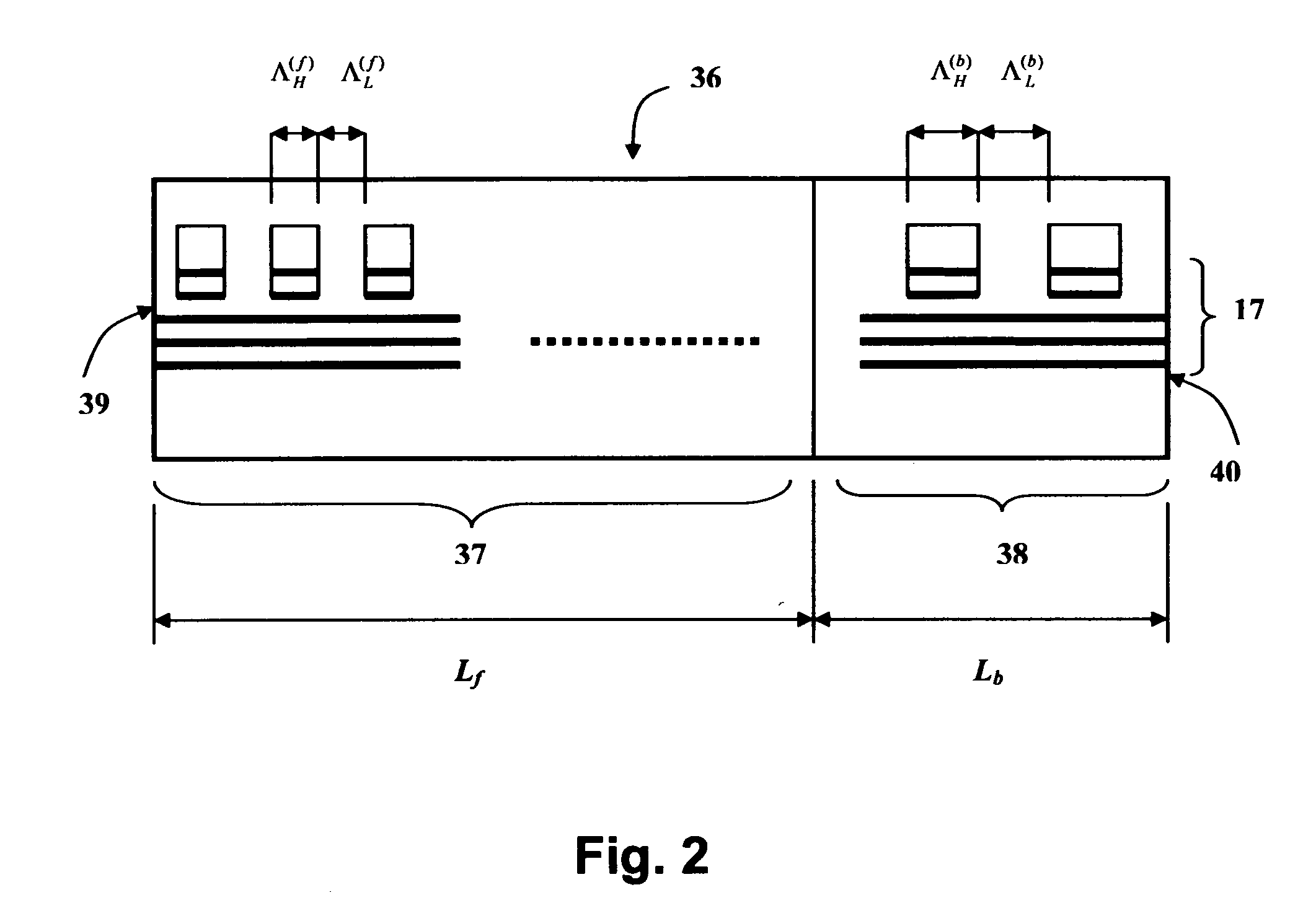
[0032] A schematic cross section through a complex-coupled DFB laser device 36 according to the present invention is shown in FIG. 2. In FIG. 2, the laser structure is same as the one shown in FIG. 1, although the detailed layer structure is not shown, and the rectangular shape grating is used instead of trapezoidal shape grating (which is used in FIG. 1), just for the sake of simplicity.

[0033] The laser cavity comprises two sections 37 and 38, comprising complex-coupled gratings which have different Bragg wavelengths; A front section 37 of the two cavity sections, having a length of Lf and a Bragg wavelength of λBf, and a back section 38, having a length of Lb and a Bragg wavelength of λBb, wherein λBb>λBf and Lf>Lb. Both front facet 39 and back facet 40 are AR coated, eliminating facet reflections. The lengths of the two cavity sections are selected such that lasing feedback is mainly provided by the front cavity section: The lasing mode is obtained at the longer wavelength side o...

fourth embodiment

[0038]FIG. 8 is a perspective view to show the construction of a complex-coupled DFB laser according to the present invention. The laser cavity consists of a uniform grating and two different buried hetero (BH) mesa widths. The front BH mesa section 43 (length Lf) has a smaller width of Wf and the back BH mesa section 44 (length Lb) has a larger width of Wb.

[0039] It has been shown that the effective index increases with increasing the BH mesa width, in the article by M. Möhrle, A. Sigmund, R. Steingrüber, W. Fürst, and A. Suna, “All active tapered 1.55-μm InGaAsP BH-DFB laser with continuously chirped grating”, IEEE Photon. Technol. Letters, vol. 15, no. 3, pp. 365-367, March 2003. Similarly to the third embodiment, the Bragg wavelength of the back cavity section can be made larger than that of the front cavity section. Therefore, the same effect as that in the third embodiment is expected.


PUM


Abstract

The invention provides a distributed feedback semiconductor laser, having (1) a controlled complex-coupling coefficient which is not affected by grating etching depth variation, and (2) facet power asymmetry with no facet reflection which eliminates a random effect of facet grating phase. The device comprises a multiple-quantum-well active region, and a complex-coupled grating formed by periodically etching grooves through a part of the active region. The semiconductor materials for a barrier layer where the groove etching is to be stopped, a regrown layer in the etched groove, and a laser cladding layer, are chosen all the same, so as to form an active grating entirely buried in the same material, providing a complex-coupling coefficient which is defined independently of the etching depth. The second feature, “facet power asymmetry”, is provided by composing the laser cavity of two sections (“front” and “back” sections) having different (“front” and “back”) Bragg wavelengths. The front cavity section, made longer than the back cavity section, provides a main feedback mechanism for lasing: The lasing wavelength is always obtained at the longer wavelength side of the Bragg stop band of the front cavity section due to “in-phase” complex coupling. By choosing the back Bragg wavelength longer than the front Bragg wavelength, the back cavity section is made to act mainly as a reflector for the lasing wavelength, so as to produce an asymmetric power distribution in the laser cavity, resulting in an increased front facet power.

Description

FIELD OF THE INVENTION [0001] This invention relates to semiconductor lasers, and in particular, to complex-coupled distributed feedback (DFB) lasers, comprising an active multi-quantum-well grating, providing a complex-coupling coefficient which is independent of grating etching depth, and asymmetric output powers from anti-reflection (AR) coated laser facets, which can completely eliminate the random effect of grating phase at laser facets. BACKGROUND OF THE INVENTION [0002] Fiber optic communication systems require high performance light source capable of generating single-mode, narrow spectral linewidth emission in the 1.3-1.56 μm wavelength range. Some of the existing semiconductor lasers, for example, InGaAsP DFB lasers can meet requirements for the light sources for optical communication systems, but fail to satisfy requirements for stable single-mode operation which is insensitive to ambient temperature change (uncooled operation) and insensitive to external optical feedback...

Claims


Application Information

Patent Timeline
IPC IPC(8): H01S3/08
CPCB82Y20/00H01S5/1064H01S5/1215H01S5/1228H01S5/3434H01S5/22H01S5/2275H01S5/3407H01S5/34306H01S5/1231
Inventor MAKINO, TOSHIHIKO
Owner APPLIED OPTOELECTRONICS
Learn More