Seperator coated with electrolyte-miscible polymer and electrochemical device using the same

a technology of miscible polymer and separator, which is applied in the field of separator, can solve the problems of insufficient discharge capacity, complicated process, and low capacity, and achieve the effects of improving battery safety, preventing deterioration in battery performance, and improving battery safety

Inactive Publication Date: 2007-03-08
LG CHEM LTD
View PDF8 Cites 21 Cited by
  • Summary
  • Abstract
  • Description
  • Claims
  • Application Information

AI Technical Summary

Benefits of technology

[0022] Owing to the above-described characteristics, the high-viscosity electrolyte formed by a process where the electrolyte-soluble polymer coated on one or both sides of the separator according to the present invention is dissolved by injection of the electrolyte can achieve not only an improvement in the battery safety but also the prevention of deterioration in the battery performance.
[0023] First, the present invention allows an improvement in the battery safety by virtue of the high-viscosity electrolyte formed by a process where the electrolyte-soluble polymer coated on one or both surfaces of the separator is dissolved by the injection of the electrolyte. Namely, oxygen generated by degradation of a cathode structure due to severe conditions, such as overcharge and high-temperature storage, will react with the inventive electrolyte having a relatively high viscosity other than the conventional electrolyte solution having high reactivity, so that the reactivity between the electrodes and the electrolyte can be reduced so as to decrease the generation of heat, thus improving the battery safety. Also, by the polar groups of the electrolyte-soluble polymer coated on the separator surface according to the present invention, the adhesion between the electrodes and the separator is increased so that the structural safety of the battery is maintained for a long period of time.
[0024] Second, the present invention allows the prevention of deterioration in the battery performance by the high-viscosity electrolyte formed by a process where the electrolyte-soluble polymer coated on one or both surfaces of the separator is dissolved by injection of the electrolyte. Namely, the electrolyte-soluble polymer dissolved in the electrolyte injected after assembling of the electrochemical device forms the high-viscosity electrolyte as described above, which shows an insignificant reduction in its ion conductivity according to an increase in its viscosity. Thus, the high-viscosity electrolyte can show ion conductivity equal to that of the prior liquid electrolytes, thus minimizing a reduction in the battery performance.
[0025] Moreover, the high-viscosity electrolyte can uniformly penetrate and distribute in the entire inside of the battery, including the surface and pores of both electrodes of the battery, the surface of electrode active materials in the battery, and the surface and pores of the separator. Thus, battery reaction by the transfer of lithium ions can occur in the entire inside of the battery, thus expecting an improvement in the battery performance. In addition, the electrolyte-soluble polymer coated on the inventive separator has an excellent affinity for the electrolyte, so that the wettability of the separator with the electrolyte can be increased, thus expecting an improvement in the battery performance.
[0026] Third, the high-viscosity electrolyte, which is formed by a process where the electrolyte-soluble polymer coated on one or both sides of the inventive separator is dissolved by the injection of the electrolyte, has an advantage in that it is easily produced since its production is possible by injecting a conventional low-viscosity electrolyte without directly injecting a high-viscosity electrolyte.

Problems solved by technology

However, the lithium secondary batteries are disadvantageous in that they have safety problems, such as firing and explosion, caused by the use of organic electrolytes, and their preparation requires a complicated process.
However, it has a relatively low capacity as compared to that of the lithium ion secondary battery, and shows insufficient discharge capacity, particularly at low temperature.
Thus, it is known that the batteries using the solid polymer electrolyte are not yet commercialized due to this inferior battery performance.
However, it is known that processes for producing the above-described two kinds of the gel-type polymer electrolytes are highly complicated and have some problems in mass production.
Also, such processes encounter limitations in the improvement of the battery performance and safety.
Namely, there is a problem in that an increase in the content of the polymer, such as PVDF-HFP, PVDF or PMMA, will lead to an improvement in the battery safety but result in great deterioration in the battery performance.

Method used


Image

  • Seperator coated with electrolyte-miscible polymer and electrochemical device using the same
  • Seperator coated with electrolyte-miscible polymer and electrochemical device using the same
  • Seperator coated with electrolyte-miscible polymer and electrochemical device using the same

Examples


reference example 1

Measurement of Viscosity and Ion Conductivity of Electrolyte in Which Electrolyte-Soluble Polymer has been Dissolved

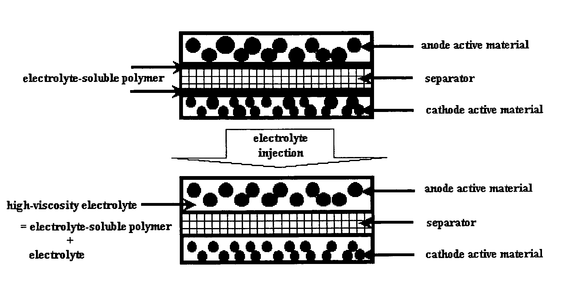
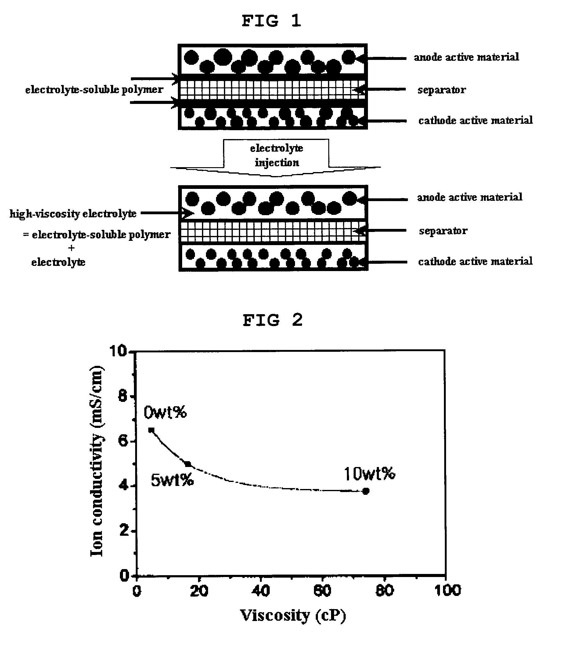
[0052] Changes in the viscosity and ion conductivity of an electrolyte with a change in the concentration of an electrolyte-soluble polymer in the electrolyte were measured. Cyanoethyl pullulan was used as the electrolyte-soluble polymer, and a 3 / 2 / 5 (weight ratio) mixture of EC / PC / DEC with a LiPF6 concentration of 1M was used as the electrolyte. The concentrations of cyanoethyl pullulan in the electrolyte were controlled to 0 wt %, 5 wt % and 10 wt %.

[0053] Changes in the viscosity and ion conductivity of the electrolyte with a change in the concentration of cyanoethyl pullulan were measured, and the measurement results are shown in FIG. 2. As shown in FIG. 2, it could be found that the viscosity of the electrolyte was greatly increased by dissolution of a small amount of the electrolyte-soluble polymer (cyanoethyl pullulan), but there was a very insignificant reduc...

examples 1-2

Production of Separator Coated with Electrolyte-Soluble Polymer and Lithium Secondary Battery Including the Same

example 1

[0054] 1-1) Production of Separator Coated with Cyanoethyl Pullulan

[0055] Cyanoethyl pullulan (degree of polymerization of about 600) was dissolved in acetone, and the solution was coated on the surface of a three-layer separator consisting of polypropylene / polyethylene / polypropylene (PP / PE / PP) by a dip coating method. Then, the coated polymer was dried at ambient temperature and dried in hot air at 100° C. so as to produce a final separator. The thickness of the electrolyte-soluble polymer film coated on the surface of the separator was about 1 μm.

[0056] 1-2) Production of Lithium Secondary Battery

[0057] (Production of Anode)

[0058] Carbon powder as a anode active material, polyvinylidene fluoride (PVDF) as a binder, and carbon black as a conductive material were added to a N-methyl-2-pyrrolidone (NMP) solvent at amounts of 93 wt %, 6 wt % and 1 wt %, respectively, so as to produce a mixture slurry for anode. The mixture slurry was applied on a 10 μm thick copper (Cu) thin film ...


PUM

PropertyMeasurementUnit
dielectric constantaaaaaaaaaa
thicknessaaaaaaaaaa
thicknessaaaaaaaaaa

Abstract

The present invention provides a separator in which an electrolyte-soluble polymer, which is soluble in liquid electrolyte, is coated on one or both surfaces of the separator, as well as an electrochemical device including the separator. Also, the present invention provides a method for producing an electrochemical device, comprising the steps of: (a) coating an electrolyte-soluble polymer, which is soluble in liquid electrolyte, on one or both surfaces of a separator; (b) interposing the separator produced in the step (a) between a cathode and an anode so as to assemble an electrochemical device; and (c) injecting a liquid electrolyte into the electrochemical device produced in the step (b). The electrochemical device, such as a lithium secondary battery, produced by the inventive method, has an improved safety while deterioration in the battery performance is minimized.

Description

TECHNICAL FIELD [0001] The present invention relates to a separator in which a polymer soluble in a liquid electrolyte is coated on one or both sides of the separator so as to improve battery safety and to prevent deterioration in battery performance, as well as an electrochemical device including the separator and a production method thereof. BACKGROUND ART [0002] Recently, interests in energy storage technology being gradually increased. As the use of batteries is enlarged to applications for the storage of energy for portable telephones, camcorders, notebook computers, personal computers and electric vehicles, efforts in the research and development of the batteries are increasingly encompass on increasingly wider variety of applications. In this view, the field of electrochemical devices receives the greatest attention, and among them, interests in the development of chargeable / dischargeable secondary batteries are focused. Recently, in order to increase the capacity, density an...

Claims


Application Information

Patent Timeline
Patent Type & Authority Applications(United States)
IPC IPC(8): H01M2/16H01M10/40H01M10/04H01M10/05H01M10/052H01M10/0569H01M10/058H01M50/403H01M50/414H01M50/457
CPCH01M2/145H01M2/16H01M2/162H01M2/1653H01M2/1673H01M2/1686Y10T29/49115H01M10/052H01M10/0565H01M10/058H01M2300/0085Y02E60/122H01M10/04Y02E60/10H01M50/403H01M50/44H01M50/46Y02P70/50H01M50/457H01M50/414H01M10/0525H01M50/409H01M50/449H01M50/411
Inventor YONG, HYUN HANGLEEKIM, SEOK KOOAHN, SOON HO
Owner LG CHEM LTD
Why Eureka
Try Eureka