Low noise amplifier with switch gain control

a low-noise amplifier and gain control technology, which is applied in amplifiers with semiconductor devices/discharge tubes, amplifier combinations, amplifiers, etc., can solve the problems of large potential capacitors, high energy consumption, and inability to integrate the whole system, so as to improve system linearity, improve system gain, and improve the effect of dynamic rang

Active Publication Date: 2007-03-15
SPREADTRUM COMM (SHANGHAI) CO LTD
View PDF18 Cites 4 Cited by
  • Summary
  • Abstract
  • Description
  • Claims
  • Application Information

AI Technical Summary

Benefits of technology

[0004] The purpose of the present invention is to introduce a low noise amplifier with switch gain control, to raise the dynamic range of the wireless receiving device, increase the system integrated level, ensure the receiving sensitivities, and prevent saturation and clog occurring at rear end circuit of low noise amplifier.
[0006] The whole system dynamic range is improved when the present invention being utilized on receiver chip in wireless communication system, or on the front end chip in radio frequency (RF) receiver. The present invention can be implemented through either CMOS technique or BiCMOS technique. The signal path selection in present invention creates different gain. When the gain changes, the impedance on either input or output amplifier terminals remains the same. Specifically when input signal is low, the switch turns on, allowing the signal runs through signal amplifying circuit, while when the input signal is high, the switch turns off, allowing the signal runs through signal attenuating circuit. Such design is able to improve system gain, improve system linearity, lower noise, and ensure receipt sensitivity, while being fully integrated.

Problems solved by technology

However since a 50 Ω impedance is required in the system, energy consumption is high, and moreover the whole system cannot be integrated.
Even when CMOS technique is used, a larger potential capacitor will be required, but with low isolation, which will induce a mismatched input signal when the switch turns off.

Method used


Image

  • Low noise amplifier with switch gain control
  • Low noise amplifier with switch gain control
  • Low noise amplifier with switch gain control

Examples


Embodiment Construction

[0014] Detail description of the drawings of the best embodiment is described as follows:

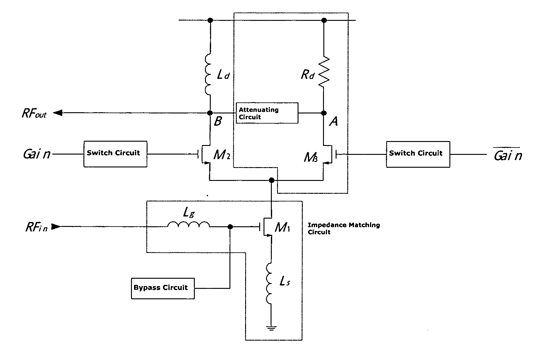
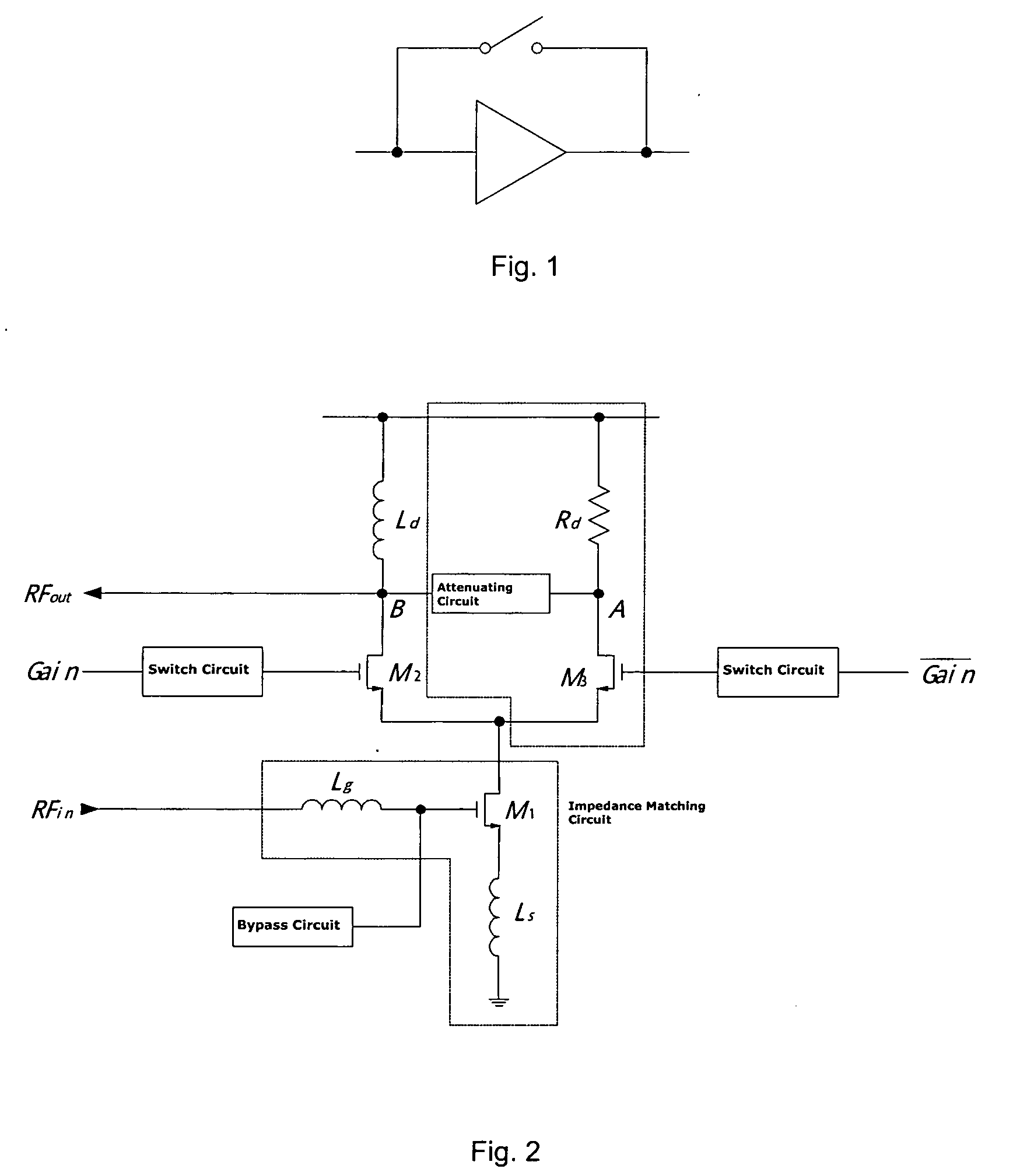
[0015]FIG. 6 shows an integrated Low Noise Amplifier with switch gain control. The Low Noise amplifier consists of an impedance matching circuit connecting a switch circuit, while the switch circuit delivers high or low signals into signal amplifying circuit and signal attenuating circuit. The amplifier also couples a current bias circuit.

[0016] As shown in FIG. 2, the impedance matching circuit consists of an inductor Lg, a voltage-current converter M1 and an inductor Ls. The impedance circuit in the present invention is also named narrow-band input matching. Under a fixed RF input signal, narrow-band input matching can achieve inhibition effect by a 50 Ω matching through resistance neutralization. The voltage-current converter M1 is made of NMOS transistor, which is also the most influential component to all aspects, including noise level, in circuit design. Improving the bias current or the...


PUM


Abstract

This invention presents a low noise amplifier with switching gain control, comprising an amplifier having an impedance matching circuit a switch circuit, a signal amplifying branch circuit, a switch control circuit, a signal attenuating circuit and a current bias circuit, wherein the switch circuit controls signal amplifying or attenuating based on the high or low of an input signal level. This invention provides low noise, great dynamic range, increased system integration, and low power consumption. This invention is used for integrated circuit wireless communication system and RF preamplifiers for receiver.

Description

FIELD OF THE INVENTION [0001] The present invention relates to a low noise amplifier with switch gain control, and more particularly to a low noise amplifier in the receiving device of a wireless radio frequency system. BACKGROUND OF THE INVENTION [0002] It is well known that the low noise amplifier is one of the essential components among wireless RF system devices. Commonly a low noise amplifier is used at the rear end of a wireless receiving device (e.g. antenna), to amplify very weak signal(s) received by the receiving device. The low noise amplifier requires a circuitry with low noise and high amplified ratio. Also when the input signal is strong it requires a more precise linearity and low gain. [0003]FIG. 1 shows a block diagram of a prior art low noise amplifier having a switch parallel connected to the amplifier. The switch forms a bias circuit. The switch turns on when the input signal is low, forming an amplified gain. The switch turns off when the input signal is high, e...

Claims


Application Information

Patent Timeline
Patent Type & Authority Applications(United States)
IPC IPC(8): H03F1/22
CPCH03F3/45183H03F2203/45464H03G1/0088H03F2203/45726H03G1/0029H03F2203/45476
Inventor ZHANG, ZHAOFENG
Owner SPREADTRUM COMM (SHANGHAI) CO LTD
Why Eureka
Try Eureka