System and methods for image segmentation in n-dimensional space

Active Publication Date: 2007-03-15
UNIV OF IOWA RES FOUND
View PDF3 Cites 98 Cited by
  • Summary
  • Abstract
  • Description
  • Claims
  • Application Information

AI Technical Summary

Benefits of technology

[0132] In accordance with yet another embodiment of the present invention, a method for simultaneous detection of multiple terrain-like surfaces of a target object is provided, where the determining an optimal closed set includes computing a minimum-cost closed set of the graph by transforming a node-weighted directed graph into an edge-weighted directed graph, including adding a start node having multiple connecting edges to each node that has a negative cost value to the weighted directed graph and cal

Problems solved by technology

Some single-purpose tools have been developed for the quantitative analysis of medical images, their usefulness is limited.
The use of these tools is often tedious and time consuming and requires an excessive amount of user interaction.
They frequently fail in the presence of disease.
Therefore, they are typically unsuitable for routine employment in the clinical care setting.
Since volumetric and/or dynamic medical images frequently cannot be reliably analyzed quantitatively using today's tools, a significant and possibly critical portion of the image information cannot be used for clinical diagnostic purposes.
There are many essential problems associated with this approach.
The most fundamental ones stem from the lack of contextual slice-to-slice information when analyzing sequences of adjacent 2-D images.
None of them, however, offers a segmentation solution that achieves optimal results.
Almost universally known, segmentation methods that perform well on the task of robust object localization usually do not perform well with respect to the accurate border/surface delineation, and vice versa.
While many of the image segmentation methods may be able to provide a locally optimal solution, they may not be able to provide a globally optimal solution.
Such methods either cannot address the globally optimal criterion at all, or compute only an approximate solution that could be arbitrarily far away from the global optimum.
These techniques are frequently iterative and their operation is based on a sequence of locally optimal steps, with no guarantee of achieving global optimality once they converge to a solution.
Results of region-based methods are frequently locally incorrect, and the performance of these methods often suffers from the problem of “leaking” into surrounding region

Method used


Image

  • System and methods for image segmentation in n-dimensional space
  • System and methods for image segmentation in n-dimensional space
  • System and methods for image segmentation in n-dimensional space

Examples


example 1

2-D

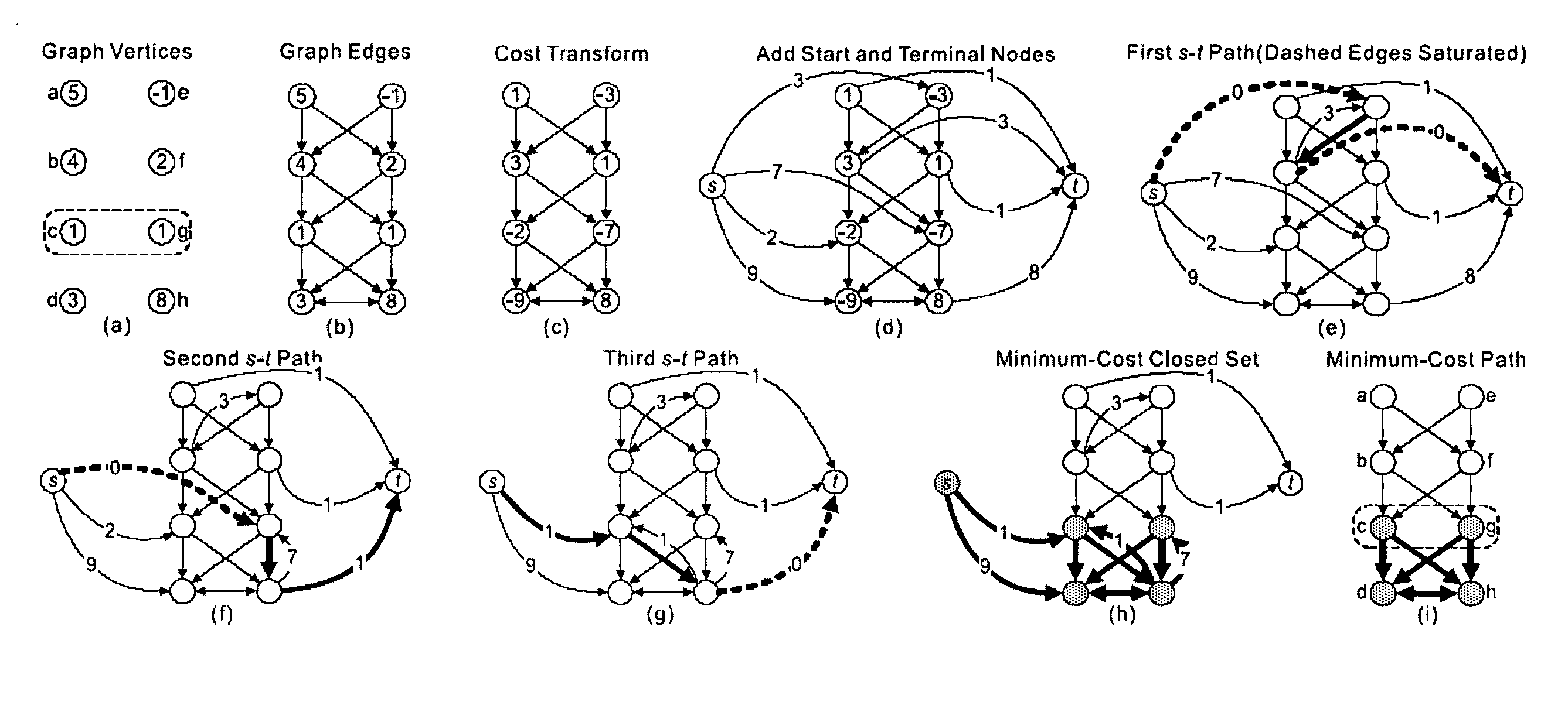
[0189] To reach an intuitive understanding of the underlying processes, a very simple 2-D example is presented corresponding to a tiny 2×4 image. The graph vertices correspond to image pixels with a cost associated with each vertex (FIG. 11(a)). The goal is to find the “minimum cost path” from left to right. The cost of the path is calculated as the sum of its vertex costs. The list of all paths in the graph includes (considering that the maximum allowed vertical distance between the two next-column vertices of the path is 1): ae, af, be, bf, bg, cf, cg, ch, dg and dh. The minimum-cost path can easily be identified as cg with the cost of 2.

[0190] In accordance with one embodiment of the present invention, the edges of the graph are preferably constructed as shown in FIG. 11(b). Cost transformation is performed by subtracting the cost of the vertex immediately below from the cost of the vertex under consideration (FIG. 11(c)). The costs of the bottommost two vertices are left un...

example 2

3-D Surface Detection

[0193] Consider the task of detecting a terrain-like surface representing the boundary of a 3-D object in a volumetric image l(x,y,z) (briefly, l). Let X, Y, and Z be the image sizes in x, y, and z dimensions, respectively. l(x, y, z) is used to denote the voxel at the spatial position (x, y, z) in the image l. For each (x, y) pair with 0≦xa)), and it intersects with each (x, y)-column at one and only one voxel. Mathematically, the surface S is called an xy-monotone surface and can be defined by a function S: {0, 1, . . . , X−1}×{0,1, . . ., Y−1}→{0, 1, . . . ,Z−1}.

[0194]FIG. 12 depicts modeling of the optimal surface detection problem. The surface orientation is shown at FIG. 12(a). Three adjacent columns in the constructed graph are shown at FIG. 12(b), with smoothness parameters Δx=2 and Δy=1. A tubular object in a volumetric image is shown at FIG. 12(c). FIG. 12(d) shows the “unfolding” of the tubular object in (c) to form a new 3-D image. The boundary of ...

example 3

Cylindrical / Tubular Surfaces

[0203] The principles from Example 2 are also applicable to detecting cylindrical / tubular surfaces, since such surfaces can always be invertibly “unfolded” to terrain-like surfaces using the cylindrical coordinate transform. Due to the circularity of a cylindrical surface, the edges of the corresponding graph should be connected in a circular manner to ensure the closure of the result. For instance, suppose an image is unfolded along the x-direction (see FIGS. 12(c) and (d)), then the smoothness constraint is also needed between the graph columns at (0, y, z) and (X−1, y, z), with y∈{0, . . . , Y−1} and z∈{0, . . . , Z−1}.


PUM


Abstract

A system and methods for the efficient segmentation of globally optimal surfaces representing object boundaries in volumetric datasets is provided. An optical surface detection system and methods are provided that are capable of simultaneously detecting multiple interacting surfaces in which the optimality is controlled by the cost functions designed for individual surfaces and by several geometric constraints defining the surface smoothness and interrelations.

Description

[0001] This application claims the benefit of U.S. Provisional Application No. 60 / 694,075, filed Jun. 24, 2005, incorporated herein by reference in its entirety.STATEMENT CONCERNING FEDERALLY SPONSERED RESEARCH [0002] The development of this invention was in part supported by a government contract of the National Science Foundation, grant CCR-9988468.BACKGROUND OF THE INVENTION [0003] Diagnostic imaging has influenced many aspects of modern medicine. The availability of volumetric images from X-ray computed tomography (CT), magnetic resonance (MR), 3-D ultrasound, positron emission tomography (PET) and many other imaging modalities has permitted a new level of understanding of biology, physiology, anatomy to be reached, as well as facilitated studies of complex disease processes. While the ability to acquire new and more sophisticated medical images has developed very rapidly in the past 20 years, the ability to analyze medical imagery is still performed visually and in a qualitativ...

Claims


Application Information

Patent Timeline
IPC IPC(8): G06K9/34G06K9/62
CPCG06K9/4638G06K9/6224G06T7/0083G06T2207/30101G06T2207/10072G06T2207/20044G06T7/0093G06T7/12G06T7/162G06V10/457G06V10/7635G06F18/2323
Inventor LI, KANGWU, XIAODONGCHEN, DANNY Z.SONKA, MILAN
Owner UNIV OF IOWA RES FOUND
Why Eureka
Try Eureka