Check patentability & draft patents in minutes with Patsnap Eureka AI!

Supercharger gear drive system

Inactive Publication Date: 2007-03-22
WOODS TERRILL WAYNE
View PDF16 Cites 20 Cited by
  • Summary
  • Abstract
  • Description
  • Claims
  • Application Information

AI Technical Summary

Benefits of technology

[0022] In accordance with the present invention the SUPERCHARGER GEAR DRIVE SYSTEM provides high reliability, low maintenance, low noise, and high levels of shock and vibration isolation, while supporting a wide variety of existing superchargers and existing internal combustion engines at minimal manufacturing effort and cost.
[0023] The crankshaft driven gear-drive engine systems are common knowledge and widely used. Supercharged engine systems are heavily utilized in the piston-driven aircraft, and heavy industrial and heavy marine industries. However, the unique challenges of a practical design for automotive applications have eluded design engineers up to the present invention. The SUPERCHARGER GEAR DRIVE SYSTEM invention has successfully resolved the unique to automotive challenge of extremely limited space, broad adaptability to fit many different engines and option packages while providing low noise, and shock and vibration isolation more commonly associated with belt-driven systems. In effect, this invention provides the commonly known advantages of high reliability and low maintenance of a crankshaft gear-driven system while also providing the advantages of low noise and shock and vibration isolation of a belt-drive system. An additional advantage of this invention is the large side load applied to the engine crankshaft and the supercharger input shaft common to belt-driven systems is totally eliminated thereby significantly increasing the reliability of both the engine and the supercharger. In addition the present invention addresses the adaptability to support a variety of superchargers, engines and engine packages at minimal manufacturing cost and effort.

Problems solved by technology

This is due to the fact turbochargers capture what would otherwise be wasted energy and use it to power the compression of the engine intake air.
The primary problem with turbocharging is the difficulty of properly matching the turbine and compressor to each particular engine in such a way as to achieve the desired performance over the engines full range of operating conditions.
The end result is turbocharger systems become so complex they do not achieve the desired cost and reliability objectives and therefore a more simple and reliable mechanically driven supercharger system is utilized.
The problem with Lee's (U.S. Pat. No. 6,308,693) integrated camshaft driven supercharger is the fact it requires a specifically designed engine with a unique camshaft drive and therefore does not apply to the present embodiment which allows superchargers to be mounted to and driven by a variety of standard engines.
The problem with the highly integrated approach is in practice automotive and marine fabricators employ many different makes and models (types) of superchargers and many different makes and models of engines.
The major disadvantage of Adachi's (U.S. Pat. No. 5,289,813) two speed drive as compared to the present embodiment is the weakness of the belt and resulting unacceptably high failure rate under racing conditions.
Again the weakness is the belt under conditions such as racing or high performance automotive and marine applications produce.
The hydrostatic variable speed drive for a supercharger is not practical (although novel) in racing or high performance automotive applications due to its high cost, high complexity and low efficiency.
This again is problematic for fabricators who need a design which is readily usable on many different superchargers and many different engines as is commonplace in racing and high performance automotive and marine applications.
An additional limitation is, the slipping wet clutch is belt driven from the crankshaft and carries the previously mentioned weakness of the belt drive.
As mentioned previously problems with the belt drive from the crankshaft to the supercharger input shaft come when the applications are severe.
Automotive racing and other forms of high performance automotive and marine applications expose a supercharger drive system to extremely high speeds and extremely rapid changes in speed and this takes belt drives beyond their present capabilities for both speed and load.

Method used


Image

  • Supercharger gear drive system
  • Supercharger gear drive system
  • Supercharger gear drive system

Examples


Embodiment Construction

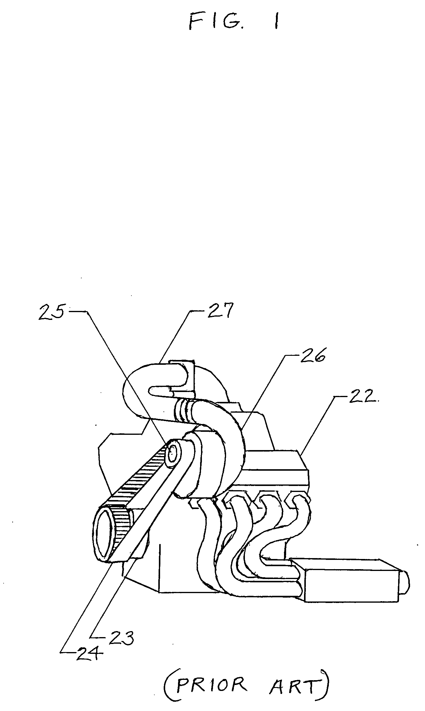
[0055] The typical supercharged engine illustrated in FIG. 1 comprises an engine 22 with crankshaft 23 providing engine torque to a belt 24 which transfers said engine torque to a supercharger single gear mesh transmission input shaft 25 which converts engine torque into boost energy via the air compressor 26 for delivery to the engine through an air intake pipe 27.

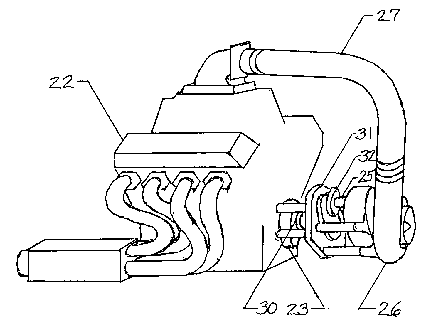
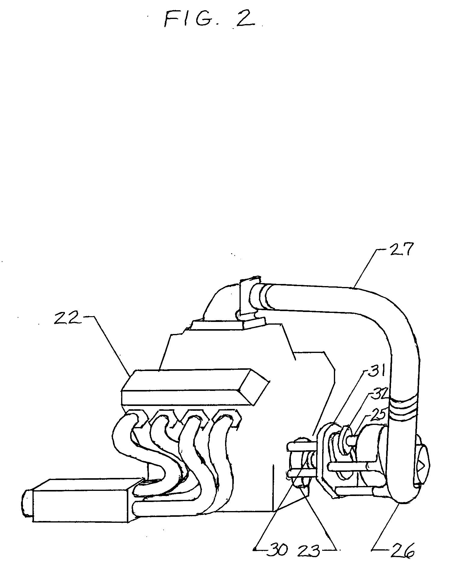
[0056]FIG. 2 illustrates claim 1 of the embodiment of the invention, a supercharged engine with a self contained gear drive applied to a standard rotation standard helix supercharger which has been turned 180° (degrees) on a horizontal plane relative to its orientation with a belt drive.

[0057] Here an engine 22 with crankshaft 23 provides engine torque to a torsional vibration isolating coupling 30 which provides engine torque to a single gear mesh gear drive 31 which passes the engine torque to an output torsional vibration isolating coupling 32 which passes the engine torque to a supercharger single gear mesh transmis...


PUM


Abstract

The invention relates generally to a drive mechanism for superchargers on internal combustion engines. More particularly, the present invention concerns a gear drive which totally eliminates the need for a belt or chain to drive the supercharger. An important object of the present invention is to provide a robust and reliable gear drive which is simple and adaptable. This allows presently available standardized mass produced superchargers to be mounted to and driven by the crankshaft of a variety of engine families thereby totally eliminating the need for a belt in the drive system. A second object of the present invention is to minimize costs by replacing the presently used belts and pulleys with additional gears internal to and integral with the supercharger housing thereby allowing the supercharger input shaft to be driven directly from the engine crankshaft.

Description

CROSS REFERENCE [0001]References CitedU.S. PATENT DOCUMENTS6,568,3765 / 2003Sonnleitner6,516,7882 / 2003Roderique6,609,5058 / 2003Janson6,308,69310 / 2001 Lee6,192,8712 / 2001Middlebrook6,082,3407 / 2000Heimark5,289,8133 / 1994Adachi, et al.5,133,3257 / 1992Winkelmann4,671,1376 / 1987Di Aragona4,519,3735 / 1985Hardy, et al.FEDERALLY SPONSORED RESEARCH OR DEVELOPMENT [0002] Not Applicable SEQUENCE LISTING, A TABLE OR A COMPUTER PROGRAM LISTING COMPACT DISC APPENDIX [0003] Not Applicable BACKGROUND OF THE INVENTION [0004] 1. Field of the Invention [0005] The present invention relates to a supercharged internal combustion engine. [0006] 2. Description of Related Art [0007] Supercharging of internal combustion engines (henceforth referred to as engine) is a well established method of obtaining greater power output from engines of a given size. Supercharging allows relatively small and lightweight engines to produce power equal to or greater than larger and heavier naturally aspirated engines. In many forms...

Claims


Application Information

Patent Timeline
IPC IPC(8): F02B33/00
CPCF02B39/04F02B33/40
Inventor WOODS, TERRILL WAYNE
Owner WOODS TERRILL WAYNE
Features
  • R&D
  • Intellectual Property
  • Life Sciences
  • Materials
  • Tech Scout
  • Unparalleled Data Quality
  • Higher Quality Content
  • 60% Fewer Hallucinations
Learn More