
Electrode for energy storage devices and electrochemical supercapacitor based on said electrode

a technology of energy storage devices and electrodes, applied in the field of electric engineering, can solve the problems of ruthenium hindering the wide application of such devices, low specific energy capacity of electrochemical supercapacitors, so as to improve service properties, extend service life, and enhance the reliability and stability of properties and other parameters

Active Publication Date: 2007-03-22
POWERMERS
View PDF15 Cites 28 Cited by
  • Summary
  • Abstract
  • Description
  • Claims
  • Application Information

AI Technical Summary

Benefits of technology

[0027] The novel electrode differs from the one described in application WO03065536 in that an alkali metal —(X), for example Li or Na, is used in the functional group (X)O—, —COO(X) of the electron-donating substituent R. Use of an alkali metal allows increasing the specific energy capacity of the energy storage device.
[0060] Besides, the electrolyte composition can contain additional compounds—stabilizers extending the service life and enhancing the reliability and stability of properties and other parameters. Thickeners that transform the electrolyte into a gel-like state can be used to improve service properties. A gel electrolyte enables one to lower the sturdiness requirements of the case and therefore to create compact energy-storage devices of various shapes.

Problems solved by technology

Nevertheless, known electrochemical supercapacitors have disadvantages, of which the most important is their low specific energy capacity.
However, the high cost of ruthenium hinders the wide application of such devices.
The maximal values of the specific energy capacity of the known supercapacitors are limited primarily by the nature of the metal oxides—the materials used in electrode manufacture, which also contributes to the high cost of these devices.

Method used


Image

  • Electrode for energy storage devices and electrochemical supercapacitor based on said electrode
  • Electrode for energy storage devices and electrochemical supercapacitor based on said electrode
  • Electrode for energy storage devices and electrochemical supercapacitor based on said electrode

Examples


Embodiment Construction

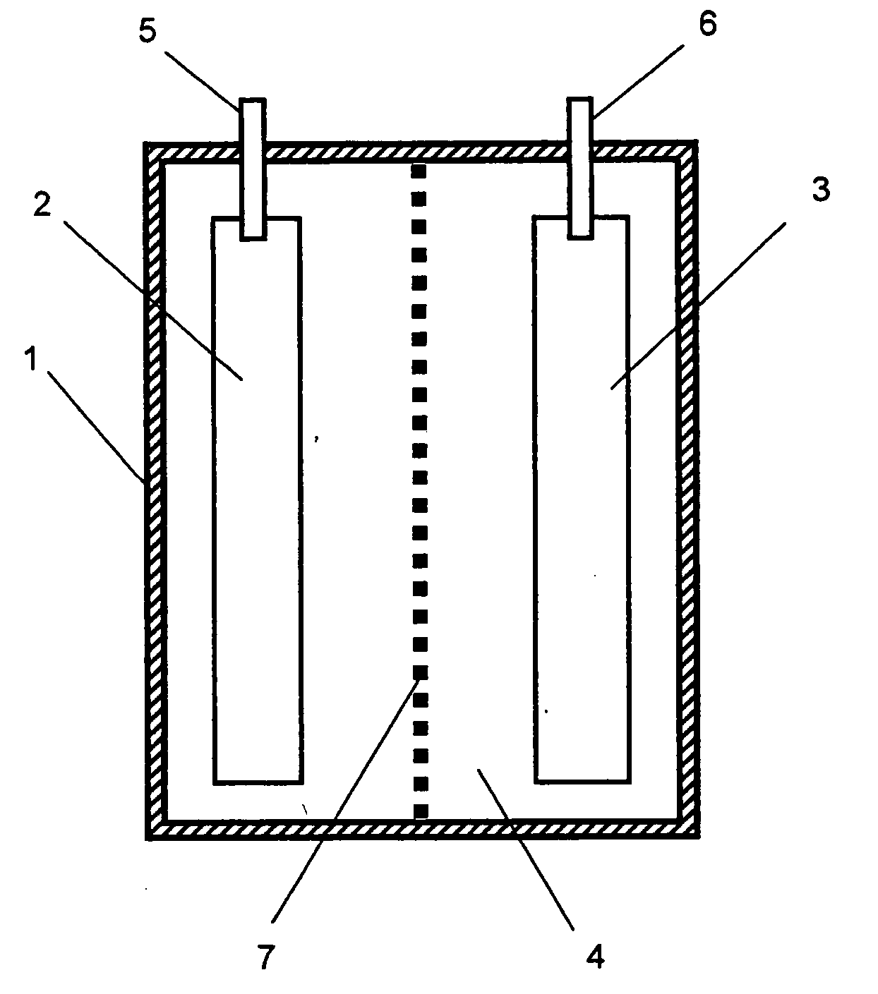
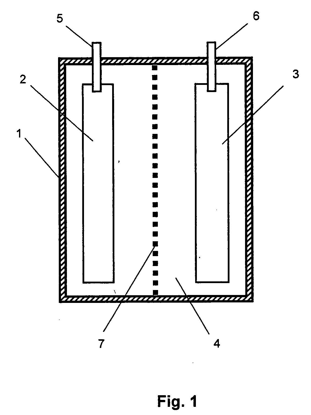
[0067] The capacitor consists of a case 1, electrodes—2 and 3, an electrolyte 4, lead terminals—5 and 6, a separator 7, as illustrated in FIG. 1.

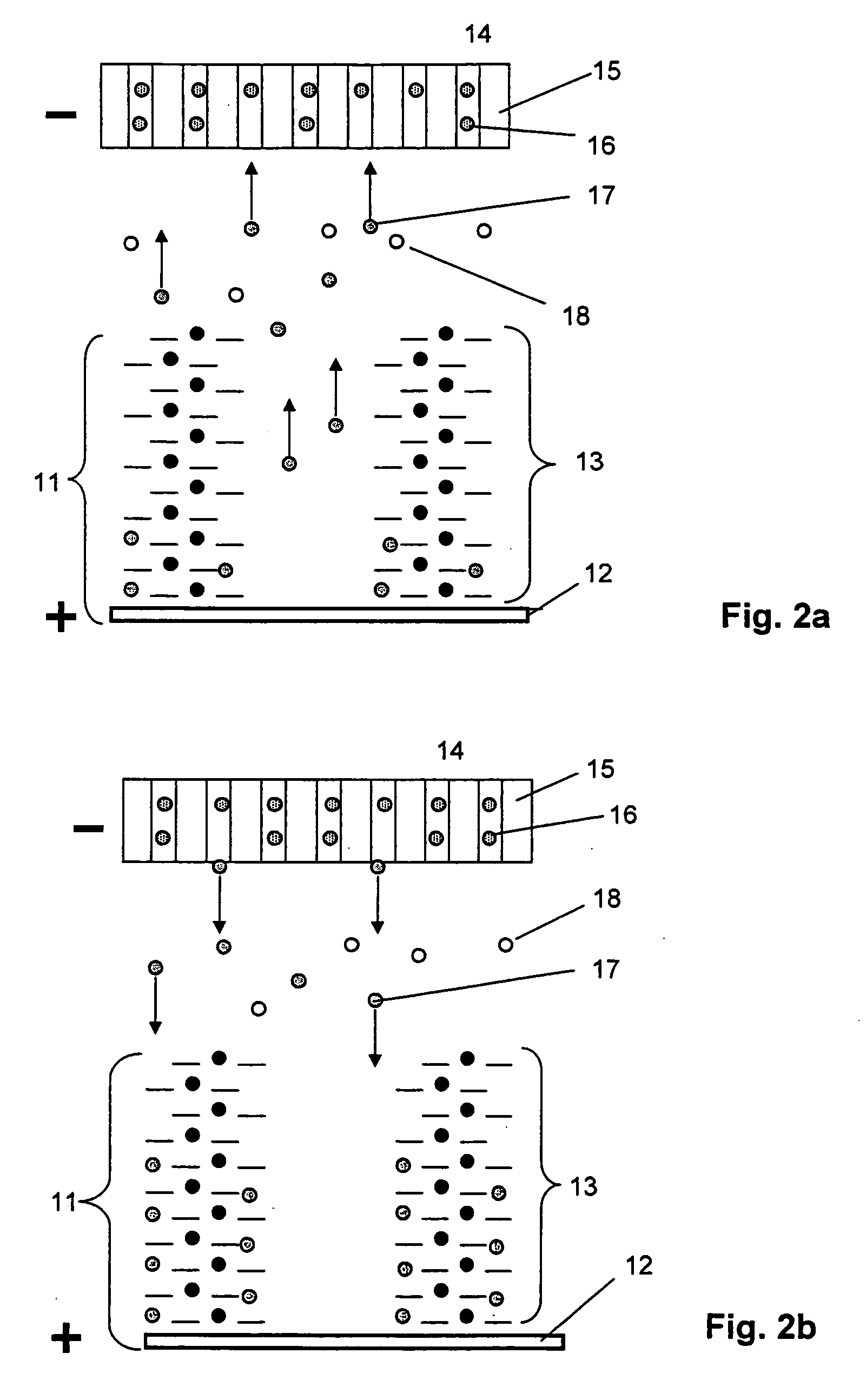
[0068] Let us consider the operation of the invention claimed herein based on an example of the electrochemical energy-storage device as shown in FIG. 2, in which the function of a positive electrode is performed by an electrode 11. Any of said redox polymers 13 having group LiO— or —COOLi as R can be deposited onto a conducting substrate 12, while the function of a negative electrode is performed by a lithium electrode 14 in which metal lithium 16 is implanted in a carbon base 15. The device is filled with an electrolyte containing one of the above-described lithium salts as a compound used for the creation of ionic conductivity of the electrolyte. The salt of the electrolyte is schematically shown in the form of lithium cations 17 and anions 18.

[0069] During the charging of the device (as shown in FIG. 2a) positive and negative potentia...


PUM


Abstract

An electrode comprises an electrically conductive substrate, a layer of energy accumulating redox polymer deposited onto the substrate, the redox polymer comprising a polymer metal complex with a substituted tetra-dentate Schiff's base selected from the group: poly-[Me(R, R′—Y)], wherein Me is a transition metal; Y is a bridge group binding the atoms of Nitrogen in the Schiff's base; R is an electron-donating substituent comprising a functional group (X)O—, —COO(X), where (X) is an alkali metal; R′ is Hydrogen or Halogen; and wherein the polymer metal complex has the following structure: The electrochemical capacitor comprises a case housing the above-described positive electrode and a negative electrode disposed inside the case, and an electrolyte filling the space between the electrodes.

Description

FIELD OF THE INVENTION [0001] The invention claimed herein relates to electrical engineering, and more specifically, to electrodes and electrode-based energy storage devices and may be used for the creation of electrochemical energy storage devices or secondary sources of current, such as supercapacitors. BACKGROUND OF THE INVENTION [0002] Secondary sources of current make it possible to accumulate, store and release electric power to an external electric circuit. Among these secondary sources are conventional batteries, conventional capacitors and electrochemical capacitors (also called Supercapacitors or Ultracapacitors). [0003] An electrochemical supercapacitor usually comprises a hermetically sealed housing filled with an electrolyte, a positive electrode (cathode) and a negative electrode (anode) placed inside the housing, a separator, such as a membrane that separates the anode space from the cathode space and special lead terminals coupling the supercapacitor to external elec...

Claims


Application Information

Patent Timeline
IPC IPC(8): H01M4/60H01G9/042H01G9/00H01G9/155H01M4/137H01M4/38
CPCH01M4/137H01M4/362H01M4/381H01M4/388H01M4/60H01G11/50H01M14/00H01M2300/0085Y02E60/122Y02E60/13H01G11/48H01M4/602Y02E60/10H01G11/02H01M4/02
Inventor TIMONOV, ALEXANDERLOGVINOV, SERGEYPIVUNOV, DMITRY
Owner POWERMERS
Learn More