Confocal self-interference microscopy from which side lobe has been removed

a self-interference microscopy and side lobe technology, applied in the field ofconfocal self-interference microscopy, can solve the problems of long test time, unsuitable for total inspection, and electron microscopy,

Inactive Publication Date: 2007-03-29
KOREA ADVANCED INST OF SCI & TECH
View PDF2 Cites 170 Cited by
  • Summary
  • Abstract
  • Description
  • Claims
  • Application Information

AI Technical Summary

Benefits of technology

[0027] Accordingly, the present invention has been made in view of the above problems occurring in the prior art, and it is an object of the present invention to provide a confocal self-interference microscopy from which side lobes have been eliminated while reducing the size of a main beam, wherein an object having a size of several tens of nm can be observed without distortion by overcoming the limits of the above-mentioned existing confocal self-interference microscopy.

Problems solved by technology

That is, the electron microscopy has drawbacks in that it must keep the vacuum state, it requires a pre-processing procedure of a specimen, it is not appropriate for total inspection, and so on.
Furthermore, the atomic force microscopy also has shortcomings in that it may give damage on the surface of the sample, it requires a long test time, it is not appropriate for total inspection, and the like.
However, the confocal microscopy has a drawback in that the limit of the resolution is decided by the optical diffraction phenomenon since it fundamentally employs light.
However, the existing optical microscopy has not yet obtained the resolution of 100 nm or less.
However, the related art confocal self-interference microscopy has the following two problems.
First, the image distortion phenomenon is generated by side lobes.
The side lobes of the confocal self-interference microscopy cause the distortion of images.
Second, an interference pattern depending on the difference in an output location between main beams that have passed through the birefringence wave plate is generated.

Method used


Image

  • Confocal self-interference microscopy from which side lobe has been removed
  • Confocal self-interference microscopy from which side lobe has been removed
  • Confocal self-interference microscopy from which side lobe has been removed

Examples


first embodiment

[0051] [First Embodiment]

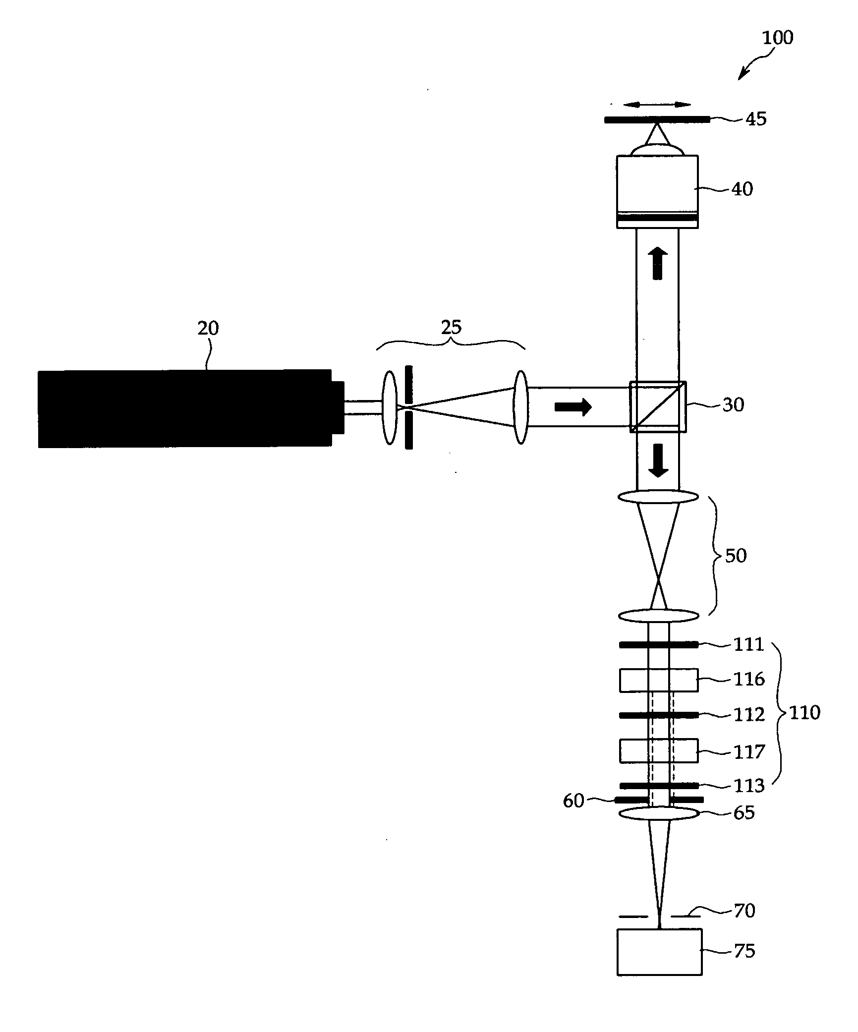
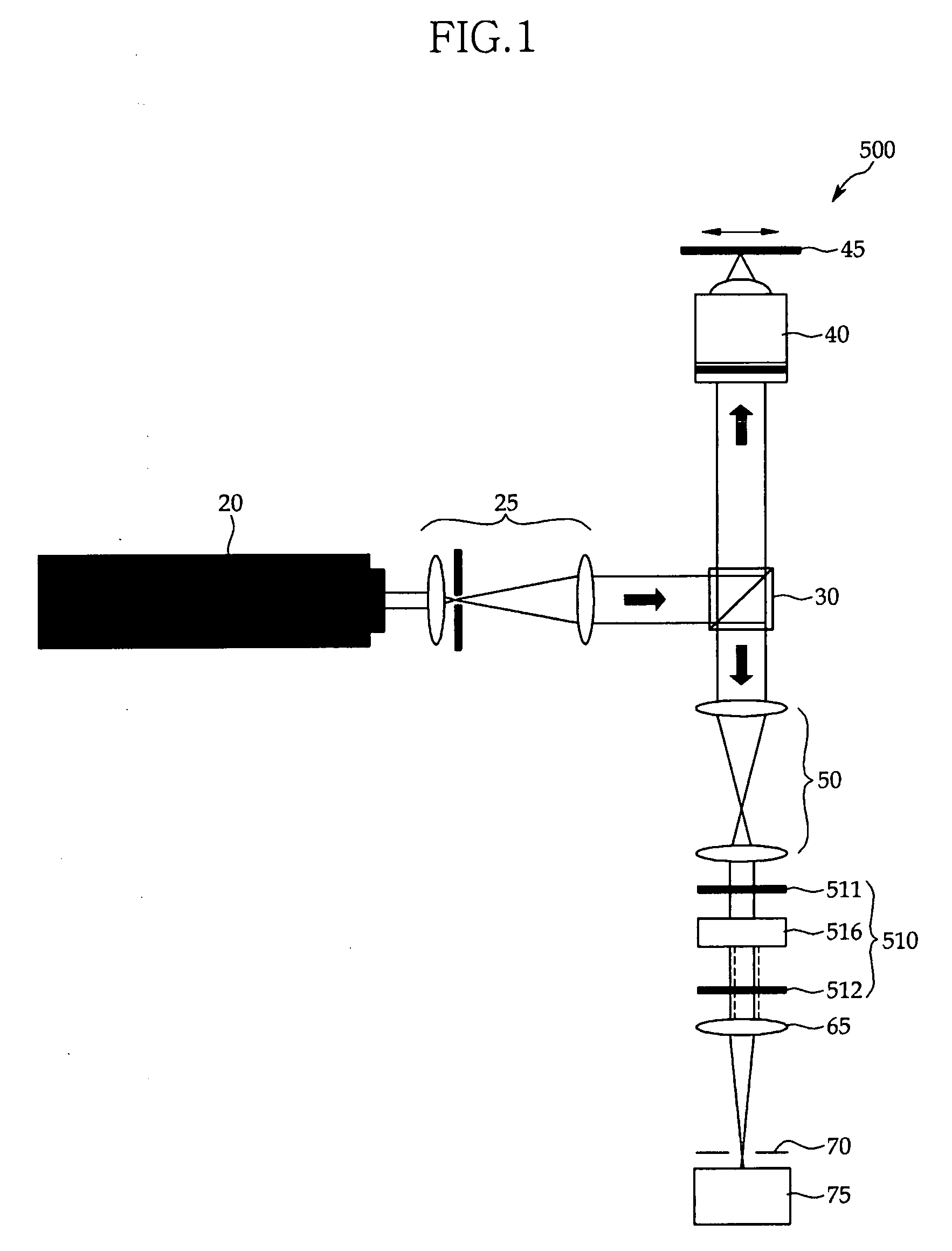
[0052]FIG. 6 shows the construction of a confocal self-interference microscopy 100 according to a first embodiment of the present invention.

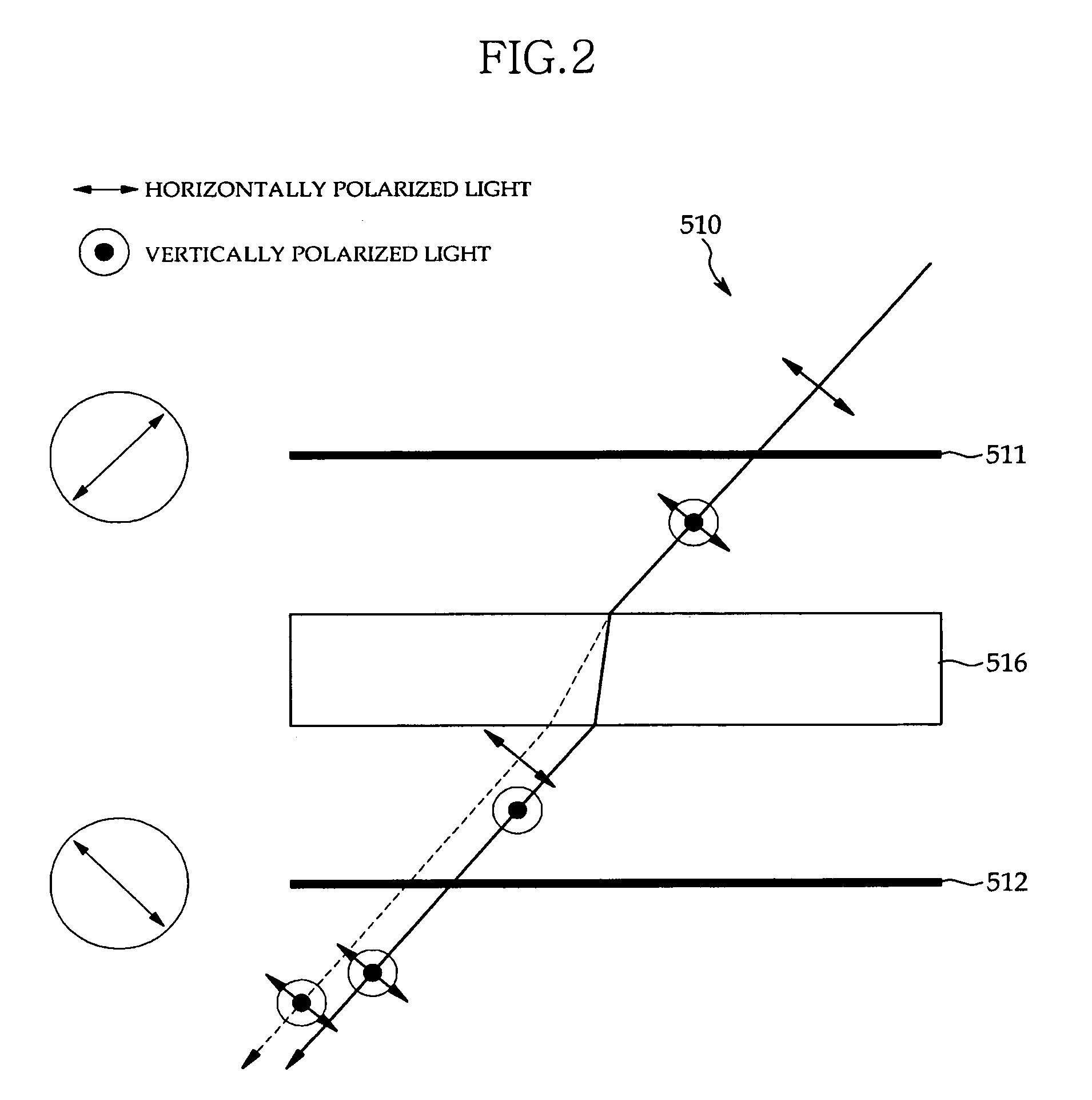
[0053] As shown in FIG. 6, the confocal self-interference microscopy 100 according to the first embodiment of the present invention includes an illumination unit 20, a beam expander 25, a beam splitter 30, a condenser 40, a specimen 45, a telescope optical system 50, an iris 60, a focusing lens 65, a pin-hole aperture 70, an image detector 75, and a self-interference optical system 110. The self-interference optical system 110 includes polarizers 111, 112, and 113, and birefringence wave plates 116, 117.

[0054] The illumination unit 20 includes a light source for illuminating the specimen 45. The light source may include a common lighting that emits light having a variety of wavelengths, a laser that emits light having a specific wavelength, or the like.

[0055] The beam expander 25 serves to convert a circular wave, whi...

second embodiment

[0088] [Second Embodiment]

[0089]FIG. 9 shows the construction of a confocal self-interference microscopy 200 according to a second embodiment of the present invention.

[0090] As shown in FIG. 9, the confocal self-interference microscopy 200 according to the second embodiment of the present invention includes an illumination unit 20, a beam expander 25, a beam splitter 30, a condenser 40, a specimen 45, a telescope optical system 50, an iris 60, a focusing lens 65, a pin-hole aperture 70, an image detector 75, and a self-interference optical system 210. The self-interference optical system 210 includes polarizers 211, 212, 213, 214 and 215, and birefringence wave plates 216, 217, 218 and 219.

[0091] The confocal self-interference microscopy 200 according to the present embodiment is the same as the confocal self-interference microscopy 100 of FIG. 6 according to the first embodiment except for the self-interference optical system 210. Description on the redundant constituent elements...

third embodiment

[0118] [Third Embodiment]

[0119]FIG. 13 shows the construction of a confocal self-interference microscopy 300 according to a third embodiment of the present invention.

[0120] As shown in FIG. 13, the confocal self-interference microscopy 300 according to the third embodiment of the present invention includes an illumination unit 20, a beam expander 25, a beam splitter 30, a condenser 40, a specimen 45, a telescope optical system 50, a relay optical system 55, an iris 60, a focusing lens 65, a pin-hole aperture 70, a image detector 75, and a self-interference optical system 110. The self-interference optical system 110 includes polarizers 111, 112, and 113, and birefringence wave plates 116, 117.

[0121] The confocal self-interference microscopy 300 according to the present embodiment is the same as the confocal self-interference microscopy 100 of the first embodiment except that the relay optical system 55 is further included between the self-interference optical system 110 and the ir...


PUM


Abstract

The present invention relates to confocal self-interference microscopy. The confocal self-interference microscopy further includes a first polarizer for polarizing reflected or fluorescent light from a specimen, a first birefringence wave plate for separating the light from the first polarizer into two beams along a polarizing direction, a second polarizer for polarizing the two beams from the first birefringence wave plate, a second birefringence wave plate for separating the two beams from the second polarizer into four beams along the polarizing direction, and a third polarizer for polarizing the four beams from the second birefringence wave plate, in the existing confocal microscopy. Optic-axes of the first and second birefringence wave plates exist on the same plane, optic-axes of the first and second birefringence wave plates are inclined from an optical axis of the entire optical system at a predetermined angle, and self-interference spatial periods of the first and second birefringence wave plates are different from each other.

Description

BACKGROUND OF THE INVENTION [0001] 1. Field of the Invention [0002] The present invention relates to a confocal self-interference microscopy from which side lobes have been removed, and more particularly, to a confocal self-interference microscopy in which the distortion of images can be reduced by eliminating side lobes from a point spread function, which occurs in an existing confocal self-interference microscopy. [0003] 2. Background of the Related Art [0004] A confocal microscopy is a microscopy in which the pin hole is disposed on a light path. from a sample to the image detector through the objective lens. The microscopy can detect beams passing through a specific cross section of the sample and obtain information about a depth of the sample as well as a plane image thereof, thereby enabling a 3-D image to be obtained. The confocal microscopy has been widely used to research structures, such as semiconductor parts, microscopically processed goods and materials, as well as biom...

Claims


Application Information

Patent Timeline
Patent Type & Authority Applications(United States)
IPC IPC(8): G02B21/06
CPCG02B21/0068G02B21/0056G02B21/00G02B21/14
Inventor GWEON, DAE GABKANG, DONG KYUN
Owner KOREA ADVANCED INST OF SCI & TECH
Why Eureka
Try Eureka