

Laser microscope
a laser microscope and microscope technology, applied in the field of laser microscopes, can solve the problems of insufficient pinhole substrates having thus-arranged pinholes, inability to observe light from samples, and inability to design such array substrates well
- Summary
- Abstract
- Description
- Claims
- Application Information
AI Technical Summary
Benefits of technology
Problems solved by technology
Method used
Image

Examples
first embodiment
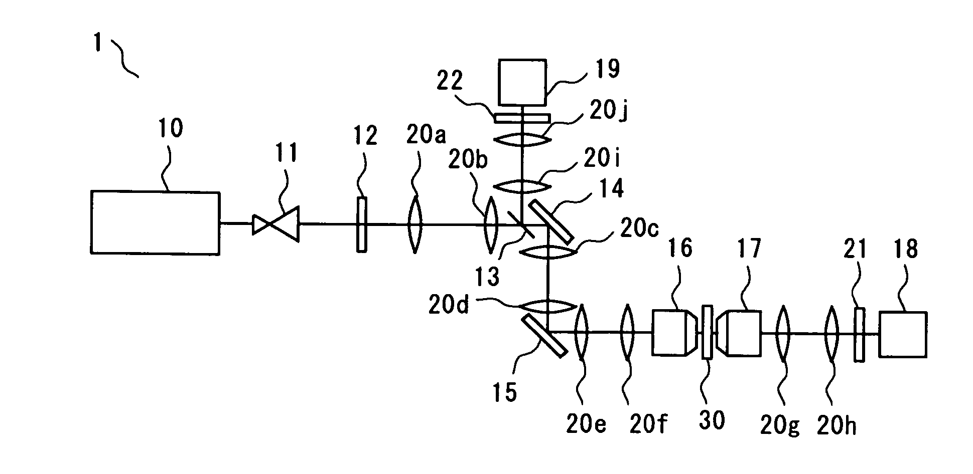
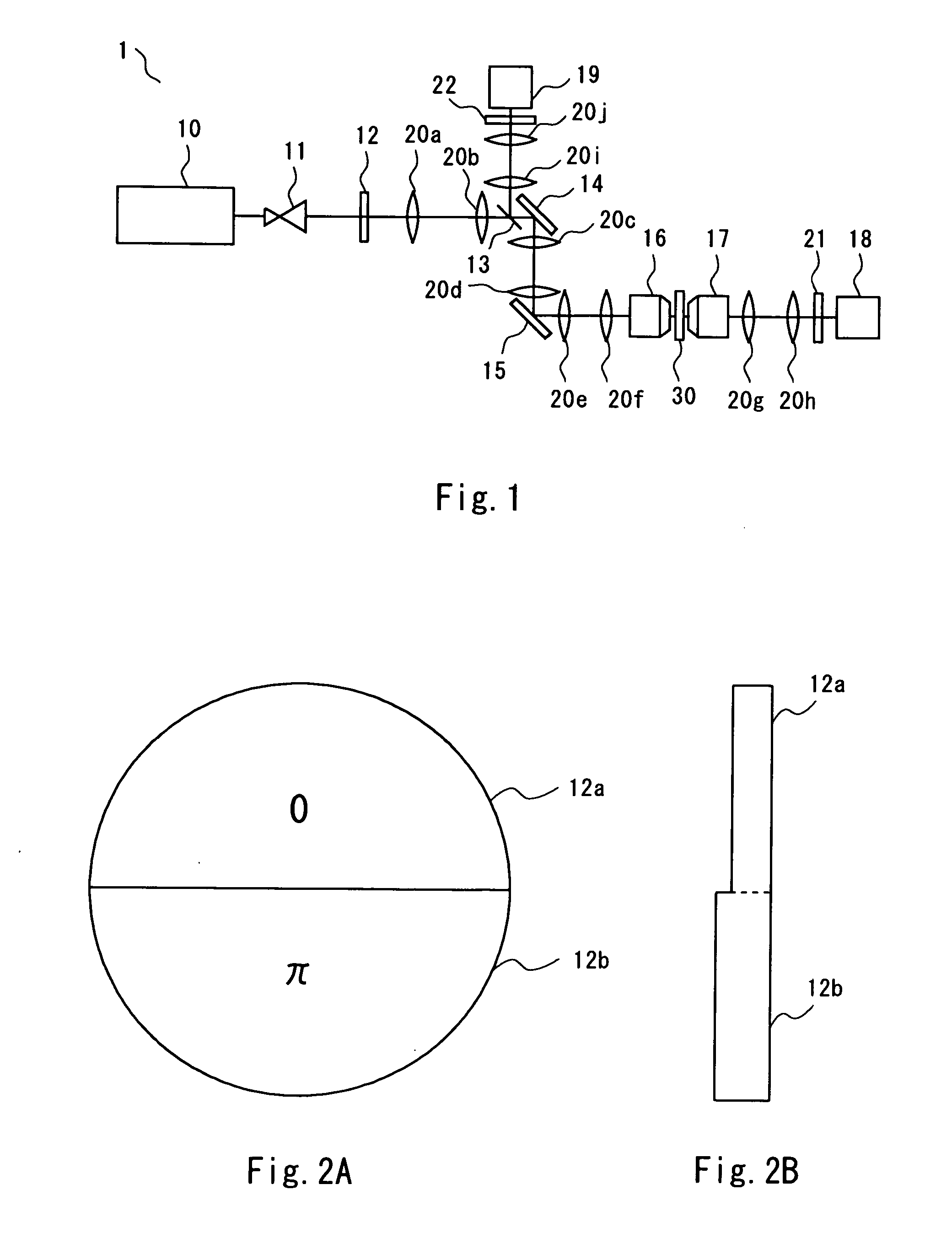
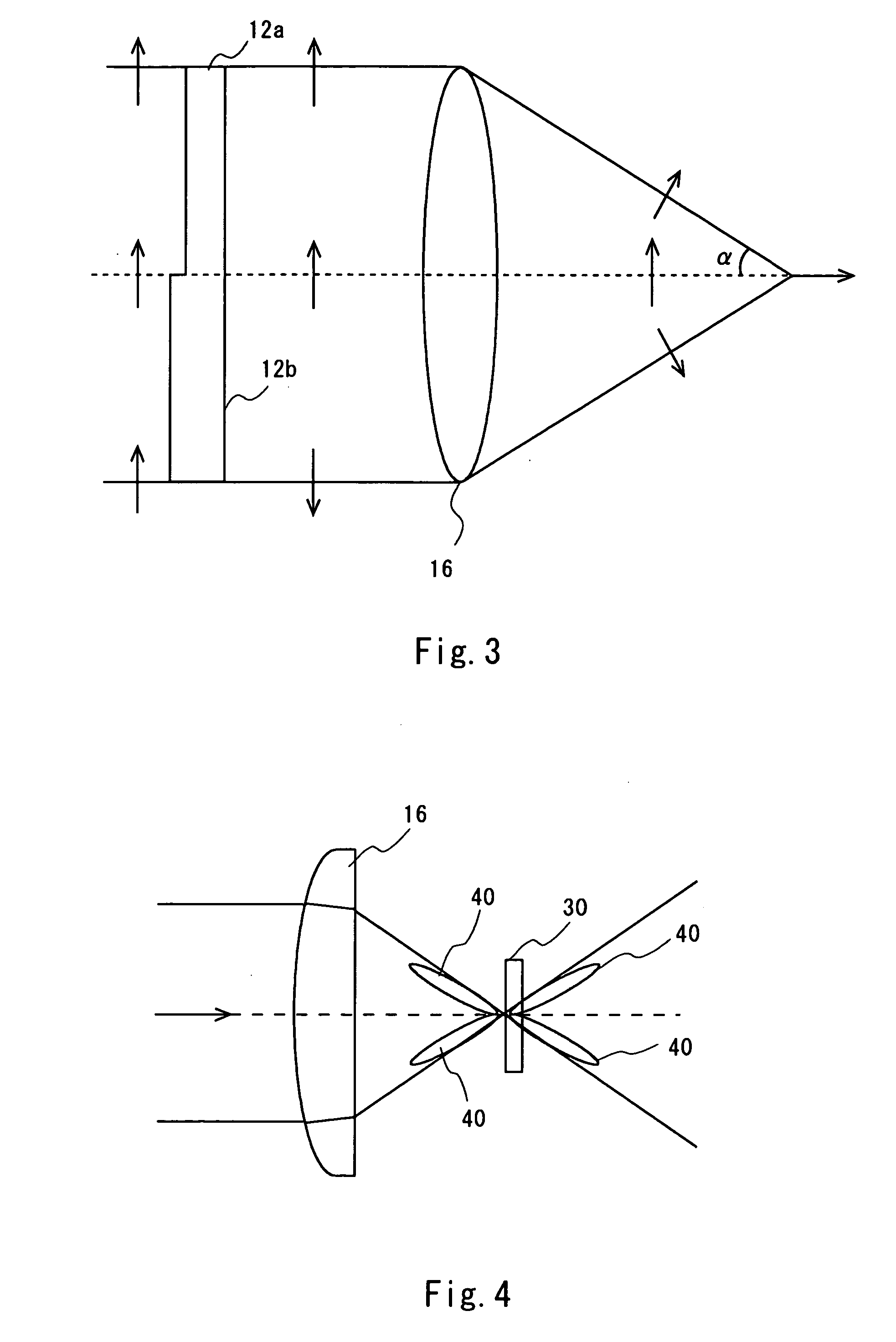
[0030] Referring to FIG. 1, description is given of a SHG microscope according to a first embodiment of the present invention. FIG. 1 is a diagram schematically showing the SHG microscope of this embodiment. The SHG microscope is an optical microscope that irradiates a sample with light of a predetermined wavelength and utilizes second harmonic generation(SHG). The SHG microscope can be utilized for observation of various samples such as a catalytic-reaction surface or microstructure of metal or a semiconductor. This microscope is especially effective for detection of a structure or function of cells or protein levels in the medical field or in the field of biotechnology. An image of second harmonic light (an image of a light intensity profile of the second harmonic light) represents an orientation distribution of molecules or the like. Based on the image, the unevenness in molecular density due to a non-equilibrium phenomenon or a distribution pattern of oriented molecules can be c...
second embodiment
[0064] Referring to FIG. 7, an SHG microscope according to a second embodiment of the present invention is described. In this embodiment, a scanning method is different from that of the first embodiment. Although the SHG microscope of the first embodiment scans the laser beam by use of the galvanometer mirror, in this embodiment, the laser beam is scanned by an XY stage. Description about the same components as those of the first embodiment is omitted here.
[0065] In this embodiment, a sample 30 is put on the XY stage (not shown). Then, the XY stage is scanned to observe and image the entire surface of the sample. In this SHG microscope as well, if the phase plate 12 of the first embodiment is used, the second harmonic light emitted backward can be detected as in the first embodiment. Thus, similar effects to the first embodiment can be obtained. Further, in this embodiment, the sample is scanned using the XY stage, so an optical system can be simplified.
third embodiment
[0066] Referring to FIG. 8, an SHG microscope according to a third embodiment of the present invention is described. A scanning method of this embodiment is different from the first embodiment. Although the SHG microscope of the first embodiment scans the laser beam by means of the galvanometer mirror, in this embodiment, the laser beam is scanned by use of a microlens array disk 25. Description about the same components as those of the first embodiment is omitted here.
[0067] In this embodiment, the microlens array disk 25 is interposed between the beam expander 11 and the lens 20a. Further, the phase plate 12 is provided between the lens 20a and the lens 20b. The laser light incident on the microlens array disk 25 is split into plural beams and then enters the lens 20a. The objective lens 16 focuses the incident multi-beam onto the sample. The multi-beam split by the microlens array disk 25 is concentrated to form multi-focal points on the sample 30 due to an image formation funct...
PUM
 Abstract
Description
Claims
Application Information