High frequency power device

a high-frequency power and power device technology, applied in the direction of corona discharge, process and machine control, instruments, etc., can solve the problems of breaking the amplifying element of the high-frequency power device, the first matching device cannot follow a high-speed change, and the reflected wave cannot be reduced, so as to achieve the effect of easy adjustment and simplified structur

Active Publication Date: 2007-04-05
DAIHEN CORP
View PDF6 Cites 12 Cited by
  • Summary
  • Abstract
  • Description
  • Claims
  • Application Information

AI Technical Summary

Benefits of technology

[0049] According to the first aspect of the invention, since the frequency of the first oscillating signal is modulated by the second oscillating signal and the first oscillating signal whose frequency is modulated is outputted, an output wave form can be varied. A degree of variation can be changed by adjusting at least one of the phase and the modulation index of the second oscillating signal. Accordingly, when the reflected wave is generated, the reflected wave power can be reduced by adjusting the reflected wave so as to be cancelled. Consequently, a risk that the amplifying element forming the high frequency output unit is broken can be reduced. Further, since an element high in its voltage resistance or a temperature resistance does not need to be selected by considering the reflected wave, the element can be miniaturized and a cost can be lowered.
[0050] According to the first aspect of the present invention, even when the reflected wave is generated by the high frequency of other high frequency power device having the different output frequency, the reflected wave can be reduced by adjusting the phase and the modulation index.
[0051] Generally, when the state of the plasma of the load is stable, even if the reflected wave is generated due to the influence of the high frequency of other high frequency power device having the different output frequency, the state of the reflected wave is hardly changed. Therefore, when the phase and the modulation index of the oscillating signal as a modulating wave are adjusted once to reduce the reflected wave by the present invention, a state that the reflected wave is reduced can be maintained without frequently changing a degree of adjustment of the phase and the modulation index.
[0052] Thus, according to the second aspect of the invention, since the operating part for manually adjusting the phase and the modulation index is provided, the reflected wave can be simply reduced without requiring a complicated control.
[0055] According to the fifth aspect of the invention, though the output frequency of other high frequency power device cannot be synchronized with the frequency of the second oscillating signal, the filter or a circuit for holding the state are not necessary, so that a structure can be the more simplified.
[0056] According to the sixth aspect to the ninth aspect of the invention, since the high frequency power device further comprises a reflected wave power calculator, calculating a reflected wave power value based on the reflected wave signal outputted from the high frequency detector and outputting a reflected wave power signal, the phase and the modulation index are easily adjusted.

Problems solved by technology

However, as described above, since the first matching device 3 drives the variable impedance element (for instance, the variable condenser, the variable inductor, etc.) to match the impedance, the first matching device cannot follow a high speed change such as the modulation of the second frequency.
Thus, the reflected wave cannot be reduced.
Further, since the generated reflected wave power reaches about 30% as high as the output as described above, the reflected wave has a large influence and may sometimes break the amplifying element in the high frequency power device.
As described above, when the plurality of high frequency power devices having the different output frequencies supply the high frequency power to the one load 5, a problem arises that the high frequency power device having the high output frequency receives an adverse effect in the amplifying element therein owing to the reflected wave by the influence of the high frequency power device having the low output frequency.

Method used


Image

  • High frequency power device
  • High frequency power device
  • High frequency power device

Examples


Embodiment Construction

[0067] Now, the detail of the present invention will be described below by referring to the drawings.

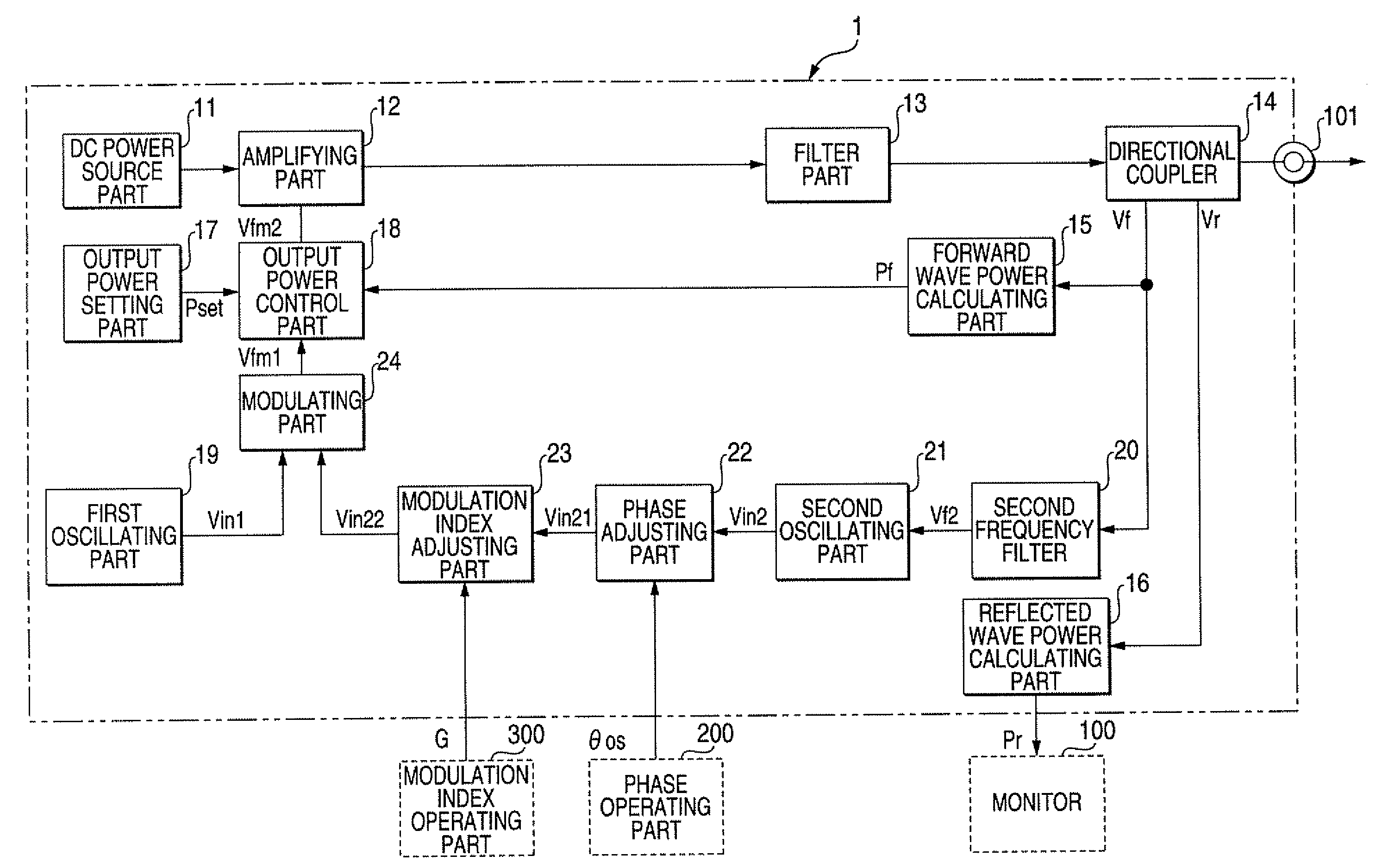
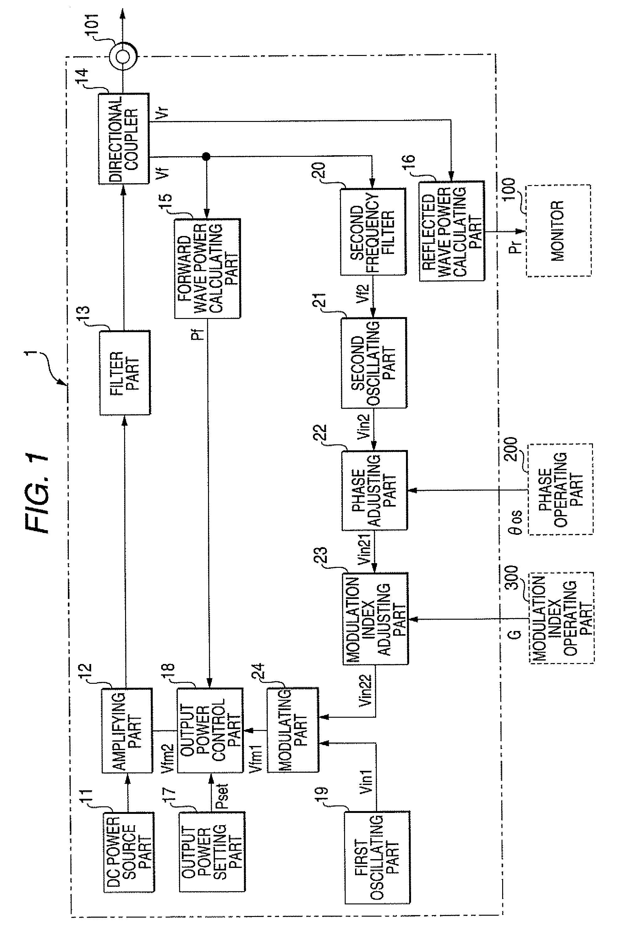
[0068]FIG. 1 is a block diagram showing the structure of a high frequency power device 1 according to the present invention.

[0069] The high frequency power device 1 includes, as shown in FIG. 1, a DC power source part 11, an amplifying part 12, a filter part 13, a directional coupler 14, a forward wave power calculating part 15, a reflected wave power calculating part 16, an output power setting part 17, an output power control part 18, a first oscillating part 19, a second frequency filter 20, a second oscillating part 21, a phase adjusting part 22, a modulation index adjusting part 23 and a modulating part 24. A first high frequency power outputted from the first high frequency power device 1 is designated by a first frequency fl, the output frequency of the first high frequency power device is designated as a first frequency f1 and the period of the first frequency is designated...


PUM


Abstract

A high frequency power device for supplying high frequency power to a load to generate plasma, includes: a high frequency detector, detecting a forward wave voltage and a reflected wave voltage in an output end of the high frequency power device to output a forward wave signal corresponding to the forward wave voltage and a reflected wave signal corresponding to the reflected wave voltage; a first oscillator, outputting a signal oscillated by a first predetermined frequency as a first oscillating signal; a second oscillator, outputting a signal oscillated by a frequency within a second predetermined frequency band as a second oscillating signal; a phase adjuster, adjusting a phase of the second oscillating signal outputted from the second oscillator; a modulation index adjuster, adjusting a modulation index of the second oscillating signal outputted from the second oscillator; a modulator, outputting a modulated signal obtained by modulating, in frequency, the first oscillating signal by the second oscillating signal whose phase and modulation index are adjusted by the phase adjuster and the modulation index adjuster respectively; and a high frequency output unit, amplifying and outputting the modulated signal outputted from the modulator or a signal obtained by controlling the output level of the modulated signal.

Description

BACKGROUND OF THE INVENTION [0001] 1. Technical Field of the Invention [0002] The present invention relates to a high frequency power device for supplying an electric power to a load such as a plasma processor for performing, for instance, a plasma etching and a plasma CVD. [0003] 2. Description of the Related Art [0004] As a plasma processing system for processing (a plasma etching, a plasma CVD, etc.) an object to be processed such as a wafer, a liquid crystal substrate or the like by using a plasma generated by the use of a high frequency power, a plasma processing system using the high frequency power of different frequencies is known as shown in FIG. 6. [0005]FIG. 6 is a block diagram showing the connecting relation of the plasma processing system using the high frequency power of the different frequencies. [0006] In FIG. 6, a usual first high frequency power device 50 is a power device for supplying a first high frequency power (refer it to as a first high frequency, hereinaft...

Claims


Application Information

Patent Timeline
Patent Type & Authority Applications(United States)
IPC IPC(8): H05F3/00
CPCH01J37/32522H02M7/48
Inventor HAMAISHI, SATORUFUKUMOTO, YOSHIKISEI, KAZUTAKA
Owner DAIHEN CORP
Why Eureka
Try Eureka