Module type multiphase inverter

a multi-phase inverter and module technology, applied in the direction of printed circuit board receptacles, electrical apparatus construction details, support structure mounting, etc., can solve the problems of undesired complexity of packaging chips into modules, surge noise, undesired complexity of connection of wires with terminals, etc., to simplify the wiring of power supplies, simplify the manufacture of inverters, and efficiently radiate heat

Active Publication Date: 2007-04-05
DENSO CORP
View PDF18 Cites 108 Cited by
  • Summary
  • Abstract
  • Description
  • Claims
  • Application Information

AI Technical Summary

Benefits of technology

[0013] In this configuration, the inverter is obtained by combining only two arm modules, and each arm module has the elements corresponding to all phases (of which the number is expressed by N). Accordingly, the manufacturing of the inverter can be considerably simplified as compared with a case where arm elements corresponding to a part of phases are assembled into each of three or more arm modules.
[0014] Further, as compared with a conventional case where each current converting element is connected with a power source through a bus bar, each common heat sink plate according to the present invention acts as a set of N bus bars. Accordingly, because only two common plates are required to electrically connect the elements of the arm modules with terminals of a power source, the use of the common heat sink plates can simplify the wiring for power supply.
[0015] Moreover, as compared with a conventional case where elements are connected with a power source through individual heat sink plates separated from one another via dead spaces, each common heat sink plate according to the present invention is equivalent to the combination of N heat sink plates having no dead space between them. Therefore, because an area composed of the N heat sink plates and opening spaces among them in the conventional case are used as an area of the common heat sink plate, an area of the common heat sink plate can be larger than a total area of the N heat sink plates. Accordingly, the common heat sink plate of each module can efficiently radiate heat generated in the elements of the module to the atmosphere, so that the use of the common heat sink plates can improve the heat radiation performance of the inverter.
[0016] Furthermore, as compared with a single module type inverter wherein all arm elements are mounted on a single heat sink plate, an area of a plane, on which the elements of each module are mounted, in the inverter according to the present invention can be reduced. Accordingly, the inverter according to the present invention can easily be installed into a motor housing, size and weight of a cooling unit for the inverter can be reduced, and connection of wires with terminals of the inverter can be simplified.
[0017] In conclusion, this inverter can have elements compactly packed and is connectable with wires having a simplified arrangement while having a both-surface cooling effect peculiar to a card type module.

Problems solved by technology

Therefore, packaging of the chips into the module is undesirably complicated.
Therefore, the leading of the terminals protruded from the side surfaces of the module and connection of the wires with the terminals are undesirably complicated.
Further, because the wires are inevitably lengthened, surge noises caused by inductance of the wirings and power loss based on resistance of the wirings are undesirably increased.
Further, because all the arm elements are disposed on a single plate, this inverter inevitably has a large plane area.
Therefore, when the inverter is packed into a motor of a vehicle, the installation of the motor in the vehicle is restricted.
Moreover, the area of each principal surface of this module is increased, and size and weight of cooling members attached to the principal surfaces of the module are undesirable increased.

Method used


Image

  • Module type multiphase inverter
  • Module type multiphase inverter
  • Module type multiphase inverter

Examples


embodiment 1

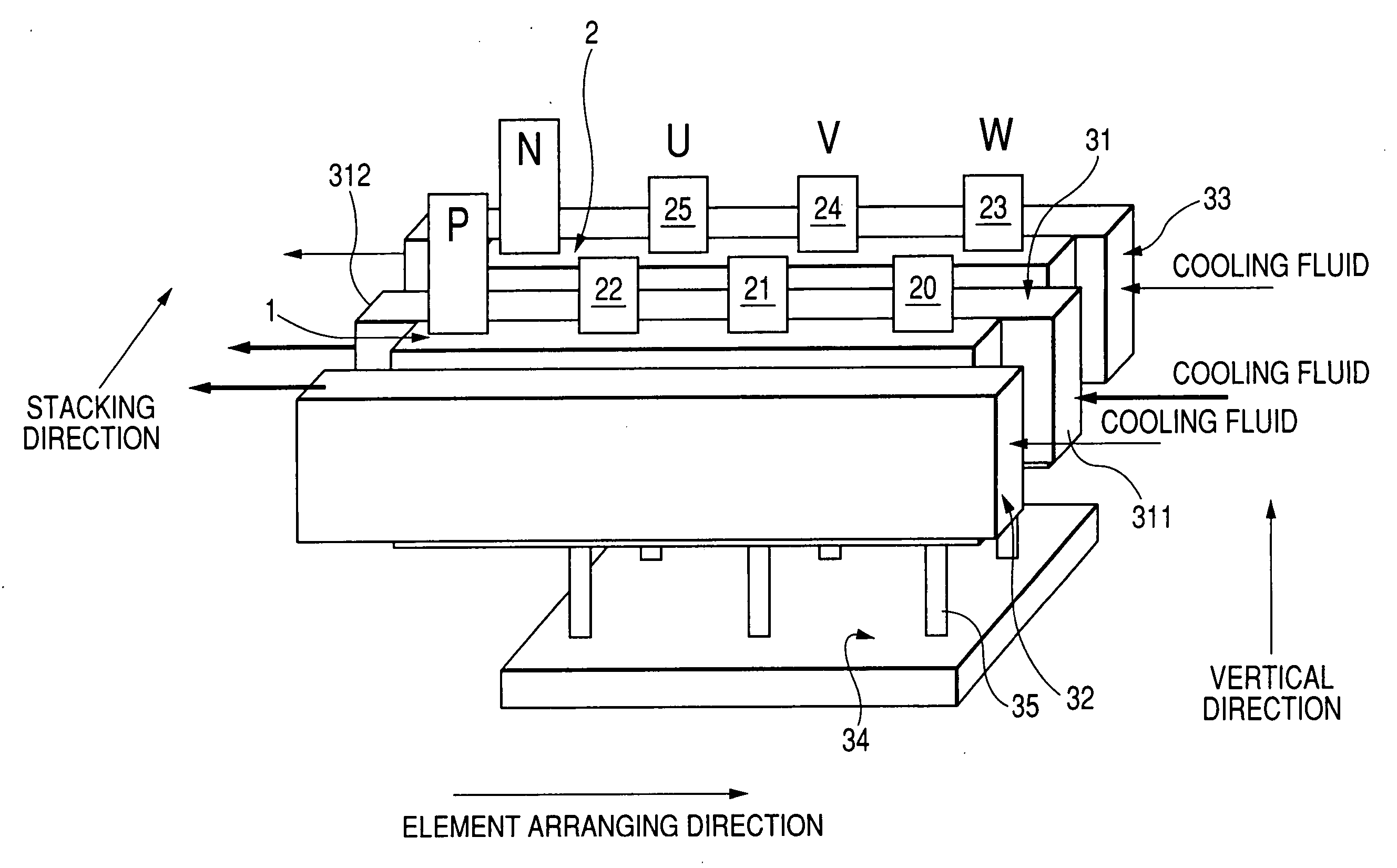
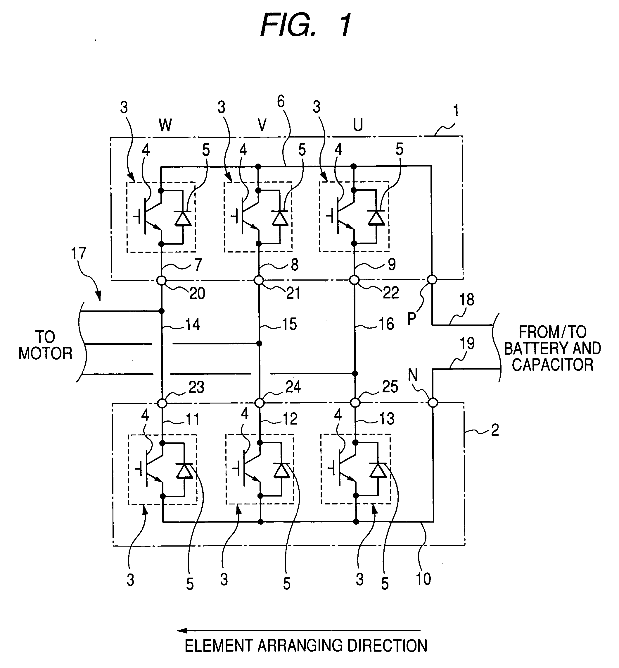
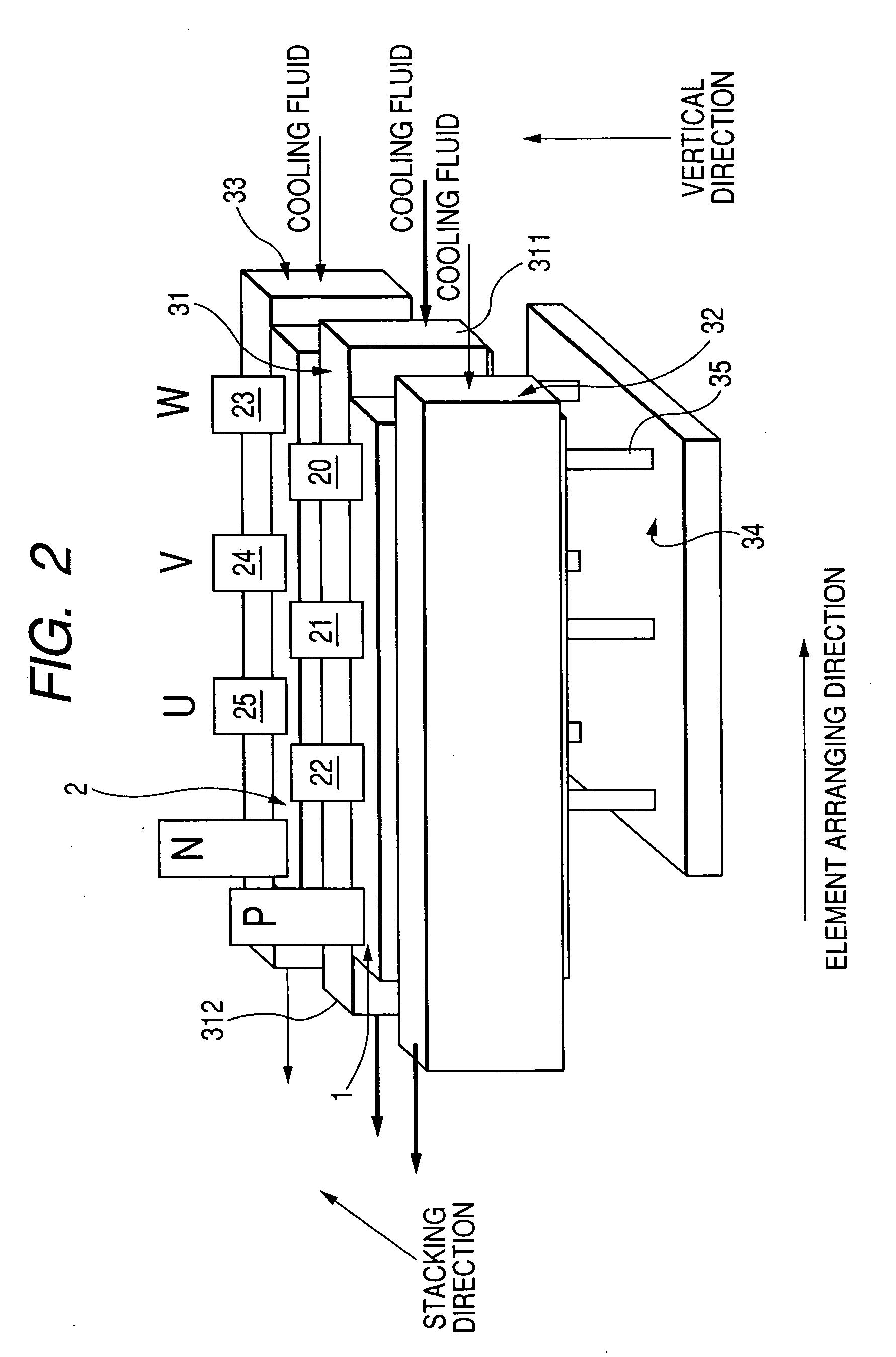
[0044]FIG. 1 is a view showing a circuit of a three-phase inverter representing a multiphase inverter according to the embodiment, and FIG. 2 is a perspective side view schematically showing the inverter shown in FIG. 1.

[0045] As shown in FIGS. 1 and 2, a three-phase inverter has a card shaped upper arm module 1 and a card shaped lower arm module 2. Each of the modules 1 and 2 has an arm element (or current converting element) 3 such as a semiconductor switching element for each of all phases U, V and W. The elements 3 of each module are disposed along an element arranging direction (or first direction) and generate a three phase alternating current from a direct current of a power source (not shown) in cooperation with the elements 3 of the other module. The modules 1 and 2 face each other along a stacking direction substantially perpendicular to the element arranging direction.

[0046] More specifically, the element (called U-phase element) 3 generating a U-phase current of the al...

modification 1

of the Embodiment

[0082]FIG. 11 is a side view schematically showing the module 1 seen from the module 2 according to a first modification. As shown in FIG. 11, the IGBT chip 4 corresponding to each phase in the module 1 may be disposed to be nearer to the terminal 20, 21 or 22 than the chip 5 of the phase. In this case, the chip 4 of each phase also becomes nearer to the terminal P than the chip 5 of the phase

[0083] Each of the plates 6 to 9 has an electrical resistance (hereinafter, called wiring resistance) for a current flowing through each of the chips 4 and 5, and heat is inevitably generated in the plates 6 to 9 by the currents of the chips 4 to 5 according to the wiring resistances of the plates. The wiring resistance of each plate for a current depends on a path length of the current in the plate. Further, a value of current flowing through the chip 4 of each phase is generally larger than that flowing though the chip 5 of the phase. When the chips 5 are disposed to be near...

modification 2

[0087]FIG. 12 is an exploded view of the module 1 according to a second modification, and FIG. 13 is a longitudinal sectional view taken substantially along line XIII-XIII of FIG. 12. As shown in FIGS. 12 and 13, the chips 4 and 5 of each element 3 are disposed adjacent to each other along the arranging direction such that the chips 4 and 5 of the module 1 are aligned with one another along the arranging direction, and the chips 4 are placed to be nearer to the terminals 20 to 22 than the chips 5, respectively. In the same manner, the chips 4 and 5 may be arranged in the module 2.

[0088] Accordingly, as compared with a case where the chips 4 and 5 of each element 3 are disposed adjacent to each other along the vertical direction (see FIG. 5), the length of the inverter along the vertical direction can be shortened. In other words, an aspect ratio of the modules can be lowered, so that the inverter can be easily disposed in a narrow space of the motor.

[0089] As another modification,...


PUM


Abstract

A multiphase inverter has two card shaped arm modules facing each other along a stacking direction. Each module has semiconductor switching elements disposed along an element arranging direction substantially perpendicular to the stacking direction, a common heat sink plate connecting direct current electrodes of the elements with one of terminals of the power source, and phase heat sink plates connecting respective alternating current electrodes of the elements with respective multiphase terminals of a motor. The elements of each module correspond to all phases of an alternating current. Each common heat sink plate forms a principal surface of the corresponding module, and the phase heat sink plates of each module forms another principal surface. The principal surfaces of each module face each other along the stacking direction.

Description

CROSS-REFERENCE TO RELATED APPLICATION [0001] This application is based upon and claims the benefit of priority of the prior Japanese Patent Application 2005-181888 filed on Jun. 22, 2005 so that the contents of which are incorporated herein by reference. BACKGROUND OF THE INVENTION [0002] 1. Field of the Invention [0003] The present invention generally relates to a module type multiphase inverter such as a three-phase inverter which generates a multiphase alternating current from a direct current and controls the driving of a multiphase alternating current motor, for example, mounted on a vehicle. [0004] 2. Description of Related Art [0005] The inventor of this specification has proposed a three-phase inverter having three half bridge modules in Published Japanese Patent First Publication No. H13-308263. In this publication, each module is formed in a card shape and has an upper arm element and a lower arm element corresponding to one of three phases. Each element is made of a semi...

Claims


Application Information

Patent Timeline
Patent Type & Authority Applications(United States)
IPC IPC(8): H05K7/20
CPCH01L25/117H02M7/003H01L2924/1305H01L2924/30107H01L2924/13055H01L2224/73265H01L2224/48247H01L2224/48091H05K7/1432H01L2924/00014H01L2924/00H05K7/20927H01L2224/40137H01L24/40H01L2924/181H01L2924/14H01L24/37H01L2224/37599H01L2224/33181H05K7/14329H01L2924/00012H01L2224/37099H01L2224/73221H01L24/36
Inventor OOHAMA, KENICHI
Owner DENSO CORP
Why Eureka
Try Eureka