Reactor containment vessel cooling equipment

a technology of containment vessel and cooling equipment, which is applied in the direction of nuclear engineering, nuclear elements, greenhouse gas reduction, etc., can solve the problems of not being able to reduce the temperature of the containment vessel, not being able to suppress satisfactorily, and the steam pressure in the containment vessel rises. achieve the effect of reducing the steam pressur

Inactive Publication Date: 2007-04-05
KK TOSHIBA
View PDF9 Cites 17 Cited by
  • Summary
  • Abstract
  • Description
  • Claims
  • Application Information

AI Technical Summary

Benefits of technology

[0005] In view of the above-identified problems, it is therefore an object of the present invention to provide nuclear reactor containment vessel cooling equipment that can reduce the steam pressure in the inside of the nuclear reactor containment vessel by utilizing the dry well coolers in an emergency situation.

Problems solved by technology

However, the flow rate of cooling water by natural circulation in the gravity-driven cooling system is considerably lower than that of cooling water in the forced circulation system so that it is not possible to condense steam to a sufficient level in the event of a loss-of-coolant accident.
Therefore, it is apprehended that the rise of the steam pressure in the inside of the nuclear reactor containment vessel that can take place in the event of a loss-of-coolant accident may not be suppressed satisfactorily.
Additionally, the currently available cooling coil has heat transfer tubes that are meandering horizontally so that it is not possible to specify the flow direction of water of natural circulation and hence it is apprehended that an unstable phenomenon can appear when the gravity-driven cooling system is activated.

Method used


Image

  • Reactor containment vessel cooling equipment
  • Reactor containment vessel cooling equipment
  • Reactor containment vessel cooling equipment

Examples


embodiment 1

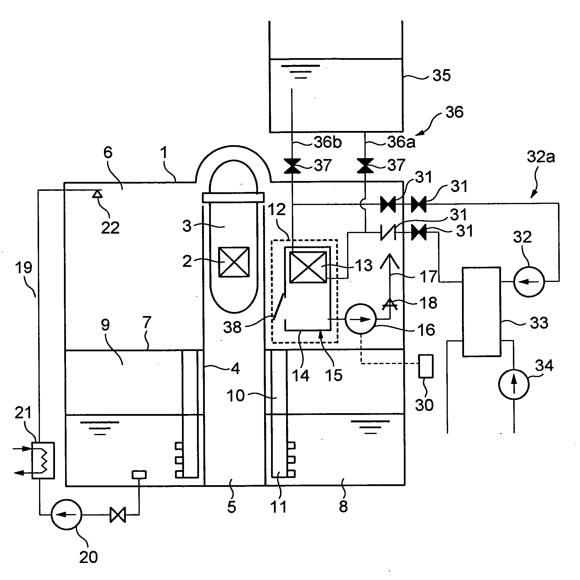
[0030] Firstly, the overall configuration of nuclear reactor containment vessel cooling equipment according to the invention will be summarily described by referring to FIGS. 1 through 3. FIG. 1 is a schematic elevational cross sectional view of Embodiment 1 of nuclear reactor containment vessel cooling equipment according to the present invention. As shown in FIG. 1, a nuclear reactor pressure vessel 3 is supported by a pedestal 4 in a nuclear reactor containment vessel 1. A reactor core 2 that holds nuclear fuel is contained in the nuclear reactor pressure vessel 3.

[0031] A lower dry well 5 surrounded by the pedestal 4, an upper dry well 6 surrounding the nuclear reactor pressure vessel 3 and a pressure suppression chamber 9 arranged under the upper dry well 6 and separated from the latter by a diaphragm floor 7 are arranged in the nuclear reactor containment vessel 1. The pressure suppression chamber 9 has a pressure suppression pool 8 in the inside thereof.

[0032] The upper dry...

embodiment 2

[0050] Now, Embodiment 2 of the present invention will be described below by referring to FIG. 4. The forced cooling water circulation system 32a that is activated in normal plant operation and the gravity-driven cooling system 36 that is operated in the event of a loss-of-coolant accident are provided as cooling systems for supplying cooling water to the dry well cooling unit 15. With this embodiment, the valves 31 and 37 shown in FIG. 1 are replaced by two three-way valves 45 that are arranged in the nuclear reactor containment vessel 1.

[0051] With this arrangement, it is possible to reduce the number of valves that operate as means for switching the forced cooling water circulation system 32a and the gravity-driven cooling system 36.

embodiment 3

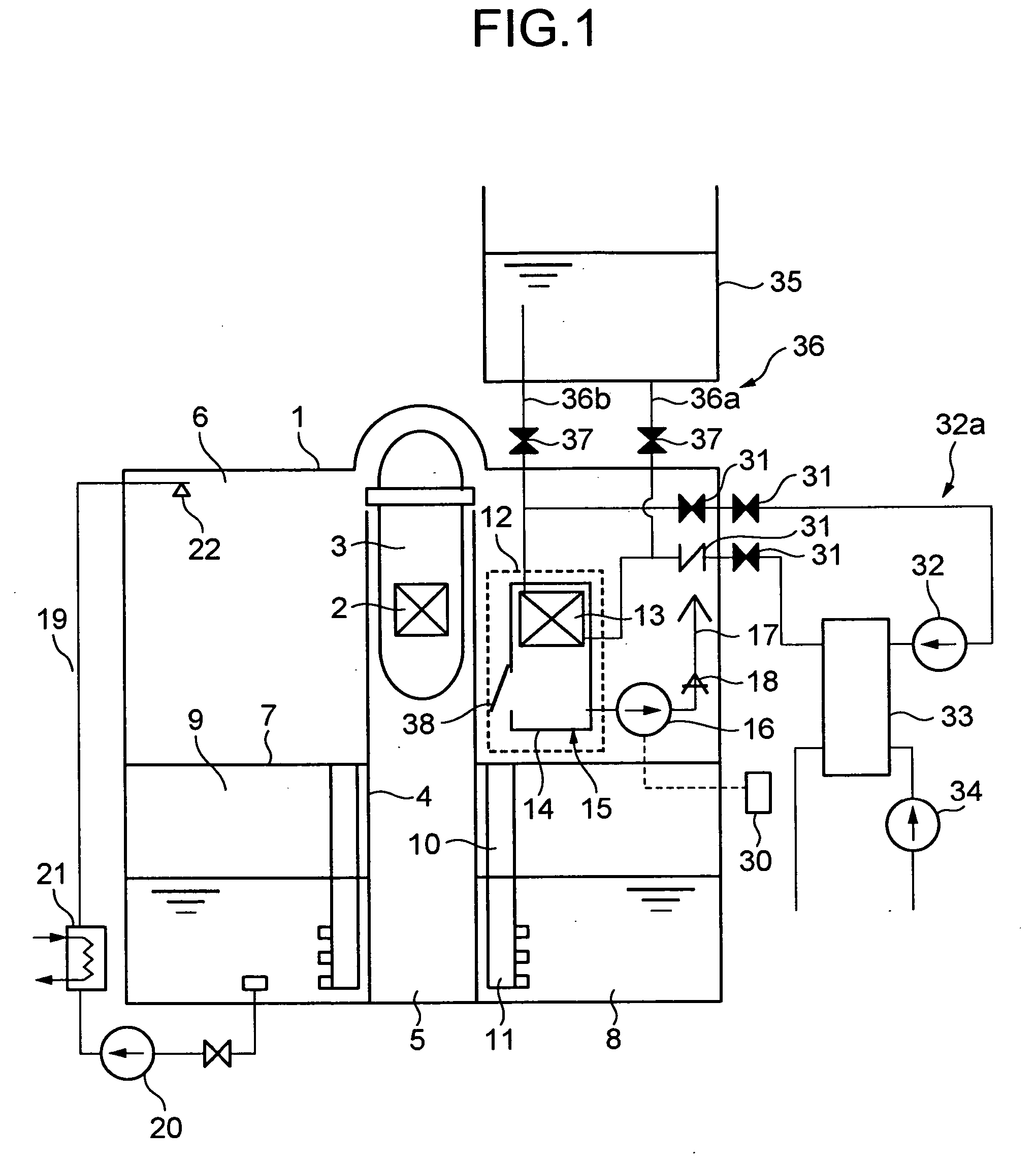
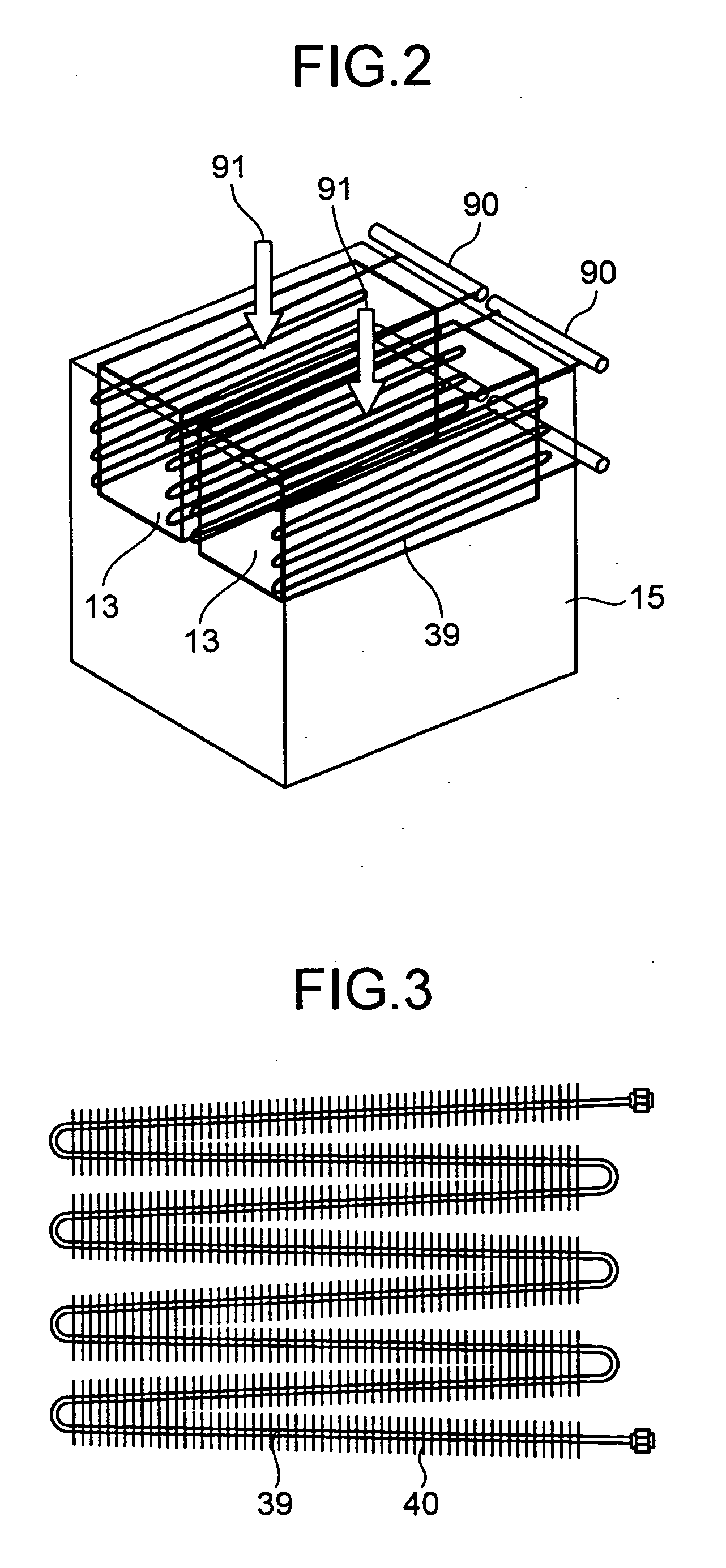
[0052] Now, Embodiment 3 of the present invention will be described below by referring to FIG. 5. With this embodiment, the cooling coils 13 of dry well coolers 12 are arranged outside the dry well cooling casing 14.

[0053] With this arrangement, in normal operation, the gas in the dry well is sucked from an upper part of the casing 14 as indicated by arrows 50 and 51, and returned into the dry well by way of the dry well cooler casing 14, a blower 16 and a duct 17. Before the gas enters the dry well cooler casing 14 by way of aperture thereof, it passes through the area surrounding the heat transfer coil 13 and becomes cooled there.

[0054] On the other hand, when an accident occurs, the power supply is suspended and the blower 16 becomes no longer operational but the condensed water produced by the cooling coil 13 falls outside the dry well cooler casing 14. Additionally, since the cooling coil 13 is arranged outside the dry well cooler casing 14, gas contained in steam does not ac...


PUM


Abstract

A nuclear reactor containment vessel cooling equipment has: a dry well cooler casing in a containment vessel, having an opening at its top and a shutter at its lower part; a heat transfer tube arranged at an upper part in the dry well cooler casing; a forced cooling water circulation system for feeding cooling water from outside of the containment vessel into the heat transfer tube by a pump; a blower for mobilizing gas around the heat transfer tube; an external pool container arranged outside the containment vessel and above the heat transfer tube and containing cooling water; and a gravity-driven cooling system to supply cooling water in the external pool container into the heat transfer tube, utilizing gravity.

Description

CROSS REFERENCES TO RELATED APPLICATIONS [0001] The present invention contains subject matter related to Japanese Patent Application No. 2005-237132, filed in the Japanese Patent Office on Aug. 18, 2005, the entire content of which is incorporated herein by reference. BACKGROUND OF THE INVENTION [0002] This invention relates to cooling equipment of a nuclear reactor containment vessel using a forced cooling water circulation system and a gravity-driven cooling system. [0003] Techniques of arranging dry well coolers in the upper dry well of a conventional boiling water nuclear power plant for the purpose of cooling the inside of the nuclear reactor containment vessel are known (see Japanese Patent Application Laid-Open Publication No. 2001-215291, the entire content of which is incorporated herein by reference). It has been discussed to utilize the dry well coolers in the event of a loss-of-coolant accident (LOCA) in order to suppress the pressure rise in the nuclear reactor containm...

Claims


Application Information

Patent Timeline
Patent Type & Authority Applications(United States)
IPC IPC(8): G21C9/00
CPCG21C9/004G21C15/18Y02E30/40Y02E30/30
Inventor TOBIMATSU, TOSHIMIIWAKI, CHIKAKOAOKI, KAZUYOSHIYOKOBORI, SEIICHIKOJIMA, YOSHIHIROAKINAGA, MAKOTONARABAYASHI, TADASHI
Owner KK TOSHIBA
Why Eureka
Try Eureka