Substrate as a ligate carrier
a technology of substrate and ligate, applied in combinational chemistry, biochemistry apparatus, chemical libraries, etc., can solve the problems of quantitative analysis of many different analytes in parallel, and the so-called “dynamic range” of the sensor, so as to reduce the surface loading of the probe
- Summary
- Abstract
- Description
- Claims
- Application Information
AI Technical Summary
Benefits of technology
Problems solved by technology
Method used
Image
Examples
example 1
Printed Circuit Board Substrates
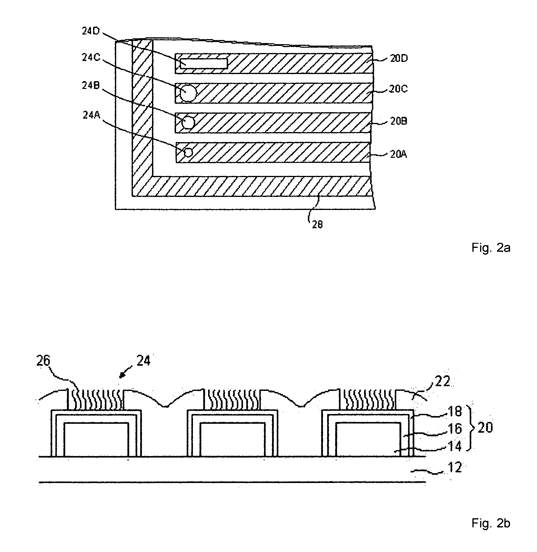
[0056] On a support plate made of epoxide woven glass fabric FR4 is applied a conductor pattern composed of fifty parallel conductor paths. FIG. 2a shows a section of this conductor path pattern. The section shows 4 of the 48 working electrodes (20A to 20D) and a portion of the counter electrode 28.
[0057] The entire conductive pattern is coated with a 15 μm to 20 μm thick passivation layer 22 (FIG. 2b) made of structurable, optically curable paint (2-component solder mask, Elpemer GL 2467 SM-DG, from the Peters company). In the passivation layer, through high-energy pulses of an excimer laser, clearances 24, 24A to 24D are introduced into the paint that serve to receive the biomolecules 26. In a passivation layer having a thickness of 15 μm to 20 μm, to remove the paint and to briefly melt the surface, about 130 20-ns pulses of an excimer laser (Lambda Physik) having a fluence of 600-1200 mJ / cm2 are needed. The melting of the surface leads to the c...
example 2
Functionalizing the Substrate Spots with Nucleic Acid Oligomers
[0061] The free substrate sites of different sizes described in example 1 are functionalized with the nucleic acid oligomers, for example via a spotting method.
[0062] The synthesis of the oligonucleotides occurs in an automatic oligonucleotide synthesizer (Expedite 8909; ABI 384 DNA / RNA synthesizer) according to the synthesis protocols recommended by the manufacturer for a 1.0 μmol synthesis. In the syntheses with the 1-O-dimethoxytrityl-propyl-disulfide-CPG support (Glen Research 20-2933), the oxidation steps are carried out with a 0.02 mol / l iodine solution to avoid oxidative cleavage of the disulfide bridge. Modifications at the 5′-position of the oligonucleotides occur with a coupling step extended to 5 min. The amino modifier C2 dT (Glen Research 10-1037) is built into the sequences according to the respective standard protocol. The coupling efficiencies are determined online during the synthesis, photometrically...
example 3
Varying the Surface Loading through Coadsorbates
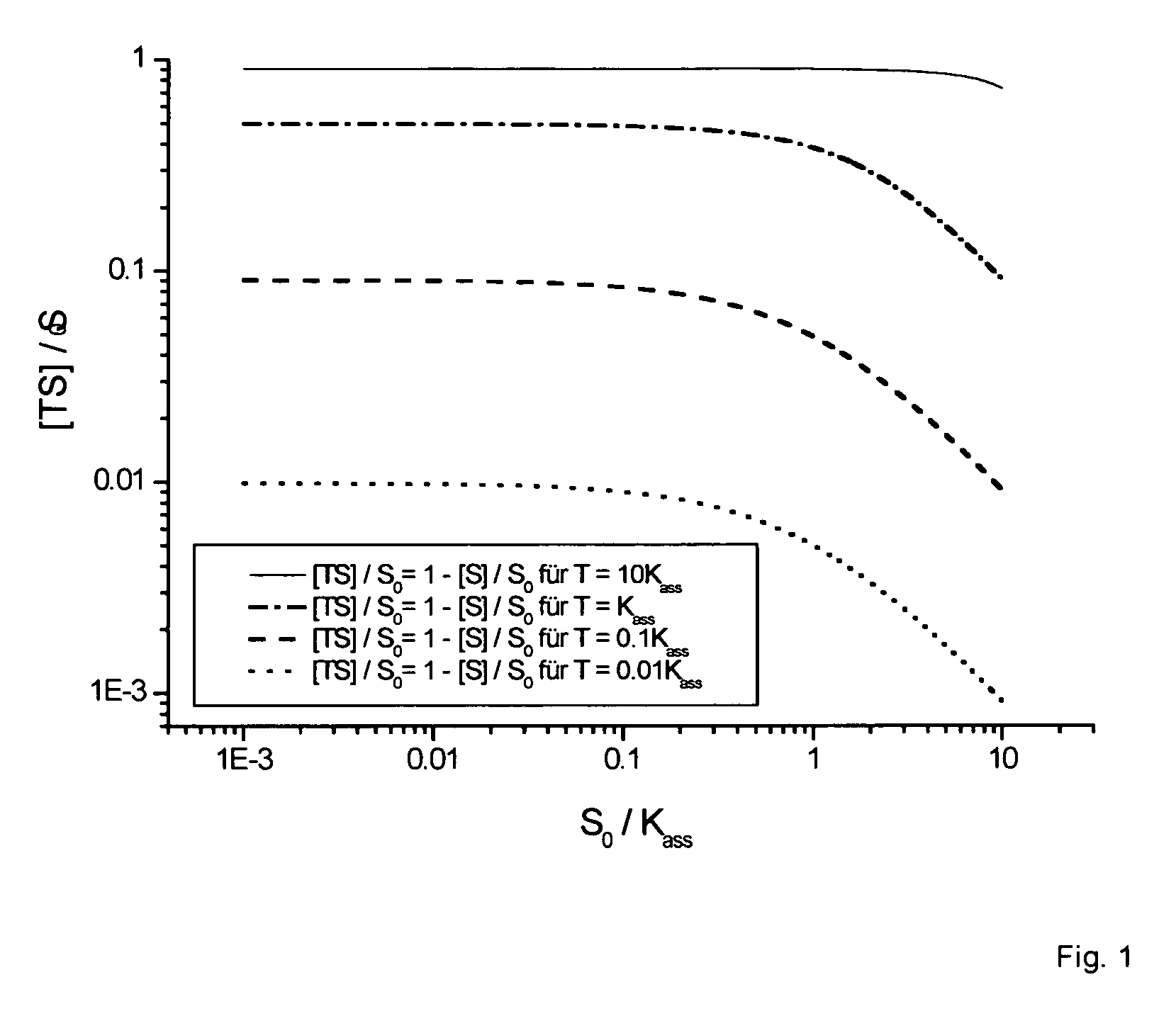
[0067] It is possible to reduce the loading density of a spot with nucleic acid oligomers in a controlled manner through coadsorption with thiols, and thus to increase the relative proportion of binding events while the target concentration and electrode size remain constant.
[0068] There are two methods to choose from for the coadsorption of thiols. In one method, the incubation solution consists of the nucleic acid oligomers (analogous to example 2) with additionally between approximately 10−5 to 10−1 molar propanethiol. This simultaneously present, free propanethiol is coadsorbed by forming an Au—S bond and thus takes up space on the sensor surface. In an alternative method, the propanethiol (10−5 to 10−1 molar in 500 mmol / l phosphate buffer) is applied in a second incubation step (30 min to 12 h) following the functionalization of the sensor surface with nucleic acid oligomers.
[0069] Through the use of propanethiol as the coadso...
PUM
| Property | Measurement | Unit |
|---|---|---|
| Surface area | aaaaa | aaaaa |
| Surface area | aaaaa | aaaaa |
| Concentration | aaaaa | aaaaa |
Abstract
Description
Claims
Application Information
 - R&D
- Intellectual Property
- Life Sciences
- Materials
- Tech Scout
- Unparalleled Data Quality
- Higher Quality Content
- 60% Fewer Hallucinations
Browse by: Latest US Patents, China's latest patents, Technical Efficacy Thesaurus, Application Domain, Technology Topic, Popular Technical Reports.
© 2025 PatSnap. All rights reserved.Legal|Privacy policy|Modern Slavery Act Transparency Statement|Sitemap|About US| Contact US: help@patsnap.com


