Multi-layer piezoelectric element

a piezoelectric element and piezoelectric technology, applied in mechanical devices, generators/motors, machines/engines, etc., can solve problems such as splinters, and achieve the effect of high durability

Inactive Publication Date: 2007-04-12
KYOCERA CORP
View PDF2 Cites 21 Cited by
  • Summary
  • Abstract
  • Description
  • Claims
  • Application Information

AI Technical Summary

Benefits of technology

[0015] It is effective to use an internal electrode that has lower specific resistance, in order to keep the device temperature from rising. However, the silver-palladium alloy has a specific resistance higher than that of pure silver or pure palladium, and the silver-palladium alloy having composition of 70% by weight of silver and 30% by weight of palladium shows a specific resistance 1.5 times that of pure palladium. In addition, resistance of an internal electrode made by sintering with a lower density becomes even higher.
[0061] This constitution provides an injection apparatus that has high durability.

Problems solved by technology

However, there have been such problems that the internal electrodes made of a metal have weak strength of adhesion with the piezoelectric material, while internal stress generated by the difference in thermal expansion of both members causes cracks in the interface between the internal electrode and the piezoelectric layer and, in the worst case, the stack would break.

Method used


Image

  • Multi-layer piezoelectric element
  • Multi-layer piezoelectric element
  • Multi-layer piezoelectric element

Examples


first embodiment

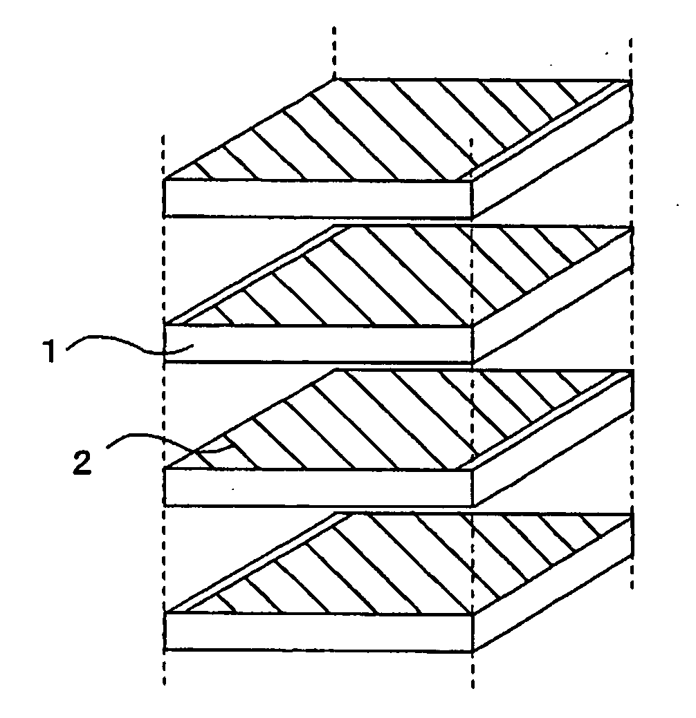
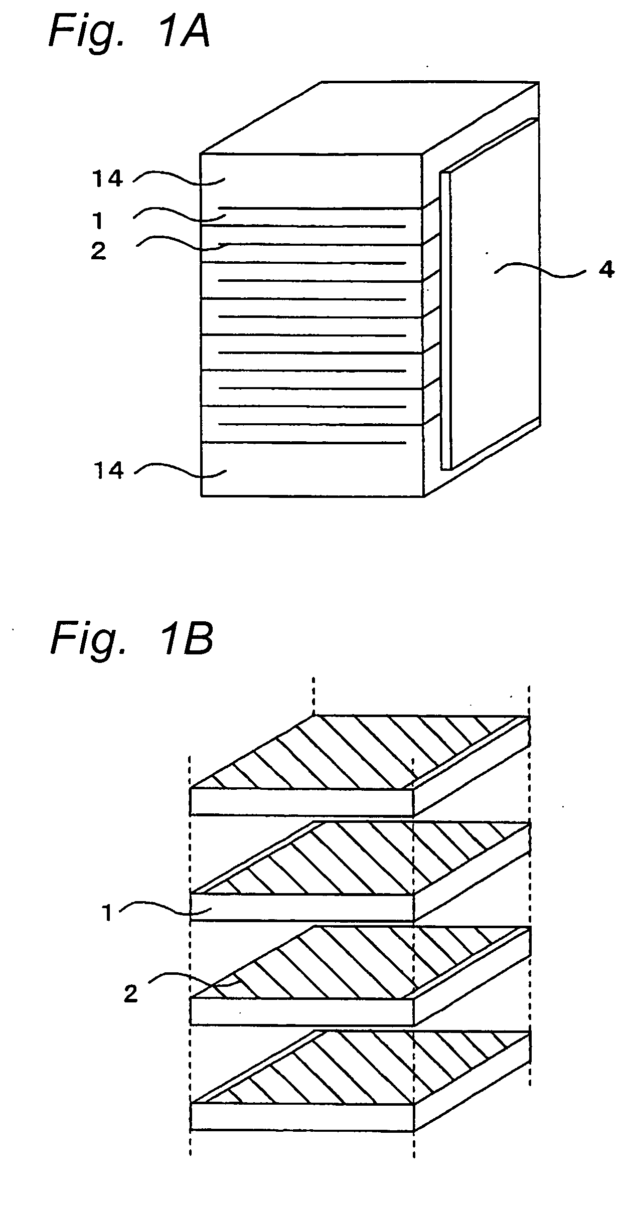
[0091]FIG. 1A is a perspective view of the multi-layer piezoelectric element according to the first embodiment of the present invention, and FIG. 1B is an exploded perspective view showing the piezoelectric layers 1 and the internal electrodes 2 being stacked one on another.

[0092] The multi-layer piezoelectric actuator of the first embodiment comprises a stack having rectangular prism shape formed by stacking a plurality of piezoelectric layers 1 and a plurality of internal electrodes 2 alternately, and external electrodes 4 formed on the side faces of the stack so as to be connected to the internal electrodes 2 in every other layer, as shown in FIG. 1A and FIG. 1B.

[0093] Specifically, an end of the internal electrode 2 is exposed on the side face whereon the external electrode 4 is formed in every other layer, so that the end of the internal electrode 2 that is exposed is electrically connected to the external electrode 4. The portion of the stack indicated with reference numeral...

second embodiment

[0136]FIG. 2A is a perspective view showing the constitution of the multi-layer piezoelectric actuator according to the second embodiment of the present invention, and FIG. 2B is a side view thereof. FIG. 3 is a sectional view of a part of the internal electrode 2.

[0137] The multi-layer piezoelectric actuator according to the second embodiment has such a constitution as the external electrodes 4 are provided on the side faces of a stack 10 having rectangular prism shape formed by alternately stacking the piezoelectric layers 1 and the internal electrodes 2 as shown in FIGS. 2A and 2B, so that one end of the internal electrode 2 is covered by an insulating material 3 in every other layer and the external electrode 4 is connected to the end of the internal electrode 2 that is not covered by the insulating material 3. The external electrode 4 is formed from a porous electrical conductor made of an electrically conductive material containing silver as the main material and glass, while...

third embodiment

[0157]FIGS. 5A and 5B show multi-layer piezoelectric element according to the third embodiment of the present invention. Fig. 5A is a perspective view and Fig. 5B is a sectional view showing the state of the piezoelectric layers, the internal electrode layers, the protective sections and the dummy layers being stacked one on another.

[0158] The multi-layer piezoelectric element according to the third embodiment has the external electrodes 4 formed on a pair of opposing side faces of a stack 30 formed by stacking the piezoelectric layers 1 and the internal electrodes 2 alternately, where the internal electrodes 2 are provided so as to electrically connect to the external electrode 4 in every other layer. In the multi-layer piezoelectric element according to the third embodiment, the stack 30 has such a constitution as inactive protective sections 20 are formed by alternately stacking the piezoelectric layers 1 and the dummy layers 21 on the top and bottom of a stacked drive section 1...


PUM


Abstract

A multi-layer piezoelectric element of high reliability and high durability, that undergoes smaller variations in the amount of displacement even when used under a high electric field and high pressure and is subject to less variations in the amount of displacement even when used in continuous operation over a long period of time is provided. The multi-layer piezoelectric element comprises a stack formed by stacking piezoelectric layers and internal electrodes alternately one on another and external electrodes formed on a first side face and on a second side face of the stack, wherein one of the adjacent internal electrodes is connected to the external electrode on the first side face and the other internal electrode is connected to the external electrode formed on the second side face, while the ratio of change in the amount of displacement of the element after undergoing continuous operation of 1×10⁹ cycles or more to the initial device dimension is not larger than 5%.

Description

TECHNICAL FIELD [0001] The present invention relates to a multi-layer piezoelectric element and injection apparatus, for example, fuel injection apparatus of automobile engine, liquid injection apparatus of ink jet printer or the like or a drive unit used in precision positioning device or vibration preventing device for an optical apparatus, and to a multi-layer piezoelectric element used as a sensor element mounted in combustion pressure sensor, knocking sensor, acceleration sensor, load sensor, ultrasound sensor, pressure sensor, yaw rate sensor or the like, or used as a circuit component mounted in piezoelectric gyro, piezoelectric switch, piezoelectric transducer, piezoelectric breaker or the like. BACKGROUND OF THE INVENTION [0002] Multi-layer piezoelectric actuators constituted from piezoelectric layers and electrodes stacked alternately one on another have been known as an example of the multi-layer piezoelectric element. The multi-layer piezoelectric actuators can be divide...

Claims


Application Information

Patent Timeline
Patent Type & Authority Applications(United States)
IPC IPC(8): H01L41/047B41J2/14F02M51/06F02M63/00H01L41/083
CPCB41J2/14274F02M51/0603H01L41/0471H01L41/0838H10N30/871H10N30/508
Inventor TERAZONO, MASAKIOKAMURA, TAKESHISAKAUE, KATSUSHI
Owner KYOCERA CORP
Why Eureka
Try Eureka