
Radar processor system and method

a radar and processor technology, applied in the field of radar processing methods and systems, can solve problems such as non-homogeneous clutter, jamming, dense target clusters, etc., and achieve the effects of improving the performance and efficiency of the algorithm, and improving the computational speed of fracta

Inactive Publication Date: 2007-04-12
THE UNITED STATES OF AMERICA AS REPRESENTED BY THE SECRETARY OF THE NAVY
View PDF2 Cites 17 Cited by
  • Summary
  • Abstract
  • Description
  • Claims
  • Application Information

AI Technical Summary

Benefits of technology

The invention is an adaptive radar processing system that uses an enhanced FRACTA algorithm, called FRACTA.E, to process radar signals. The system includes an antenna array for transmitting and receiving radar signals, and a signal processor programmed with the FRACTA.E algorithm. The FRACTA.E algorithm is enhanced with five versions, including versions that use global censoring, fast reiterative censoring, data vector segmentation, and knowledge-aided covariance estimation. These enhancements improve the computational speed and efficiency of the system, allowing for better detection performance with less training data. The system can be used in combination with other versions to achieve even greater improvements in performance.

Problems solved by technology

Radar systems such as those used for airborne applications typically have to contend with the presence of non-homogeneous clutter, jamming, and dense target clusters.
In these systems, desired signal detection and estimation is hindered by noise and interference.
However, real-world weight training data may be contaminated by undesirable impulse noise outliers, resulting in a non-Gaussian distribution of real and imaginary components.
If, however, the weight training data contains non-Gaussian noise outliers, the convergence MOE of the system increases to require an unworkably large number of weight training data samples.
The performance degradation of the SMI algorithm in the presence of non-Gaussian distributions (outliers) can be attributed to the highly sensitive nature of input noise covariance matrix estimates to even small amounts of impulsive non-Gaussian noise that may be corrupting the dominant Gaussian noise distribution.
Thus, for contaminated weight training data, convergence rate may slow significantly with conventional systems.
Fast convergence rates are important for several practical reasons including limited amounts of weight training data due to non-stationary interference and computational complexity involved in generating adaptive weights.
In other words, the time which elapses while a conventional system is acquiring weight training data and generating adaptive weights may exceed the stationary component of a given non-stationary noise environment, and an adaptive weight thus generated has become obsolete prior to completion of its computation.
Conventional signal processors assume that the weight training data has a Gaussian distribution, and therefore they do not perform as well as theory would predict when operating with real world data.
However, they still have convergence MOE's that are degraded by outliers.
Due to the lack of knowledge of an external environment, adaptive techniques require a certain amount of data to estimate the MN×MN input covariance matrix effectively.
However, the presence of outliers in the training data can skew the covariance matrix estimate such that a true target in the primary range cell is suppressed.
This problem is closely related to the existence of land-sea clutter interfaces, which cause significant degradation in airborne radar adaptive processing.
The presence of the desired target returns in the training data can severely degrade the adaptive match filter's performance, because the training data is used to estimate a weighting vector which is in the null space of the signal and interference sources that are in the training data.
Hence, if a signal that has the desired signal's steering vector is in the training data, the adaptive weight vector may null the desired signal.

Method used


Image

  • Radar processor system and method
  • Radar processor system and method
  • Radar processor system and method

Examples


Embodiment Construction

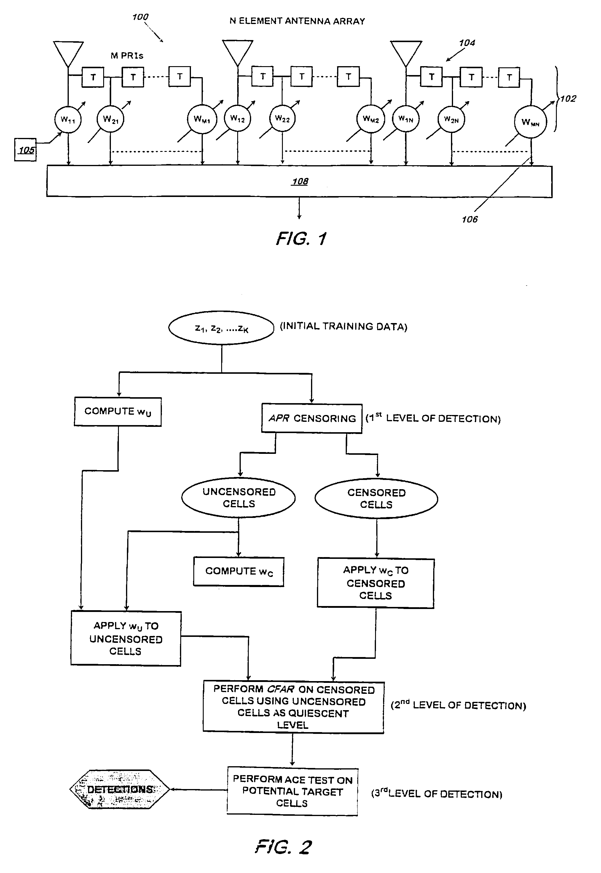
[0039] Referring now to FIG. 1, a radar system 100 includes an N-element uniform linear array 102 resulting in N Radio Frequency (RF) input channels. Each of the N array elements has M time delayed inputs 104 which are combined via adaptive linear weighting to form outputs 106 such that an output performance measure (such as signal-to-noise (S / N) power ratio) is optimized. The adaptive linear weighting is determined by a STAP processor 105. A combiner 108 accumulates the weighted outputs to form the final output power residue.

[0040] Assume that for each of these RF channels, the radar front end carries out amplification, filtering, reduction to baseband, and analog-to-digital (A / D) conversion. The output of each A / D is a data stream of in-phase and quadrature phase (I, Q) output pairs. The I and Q components represent the real and imaginary parts, respectively, of the complex valued data stream. The radar waveform is assumed to be a burst of M identical pulses with pulse repetition...


PUM


Abstract

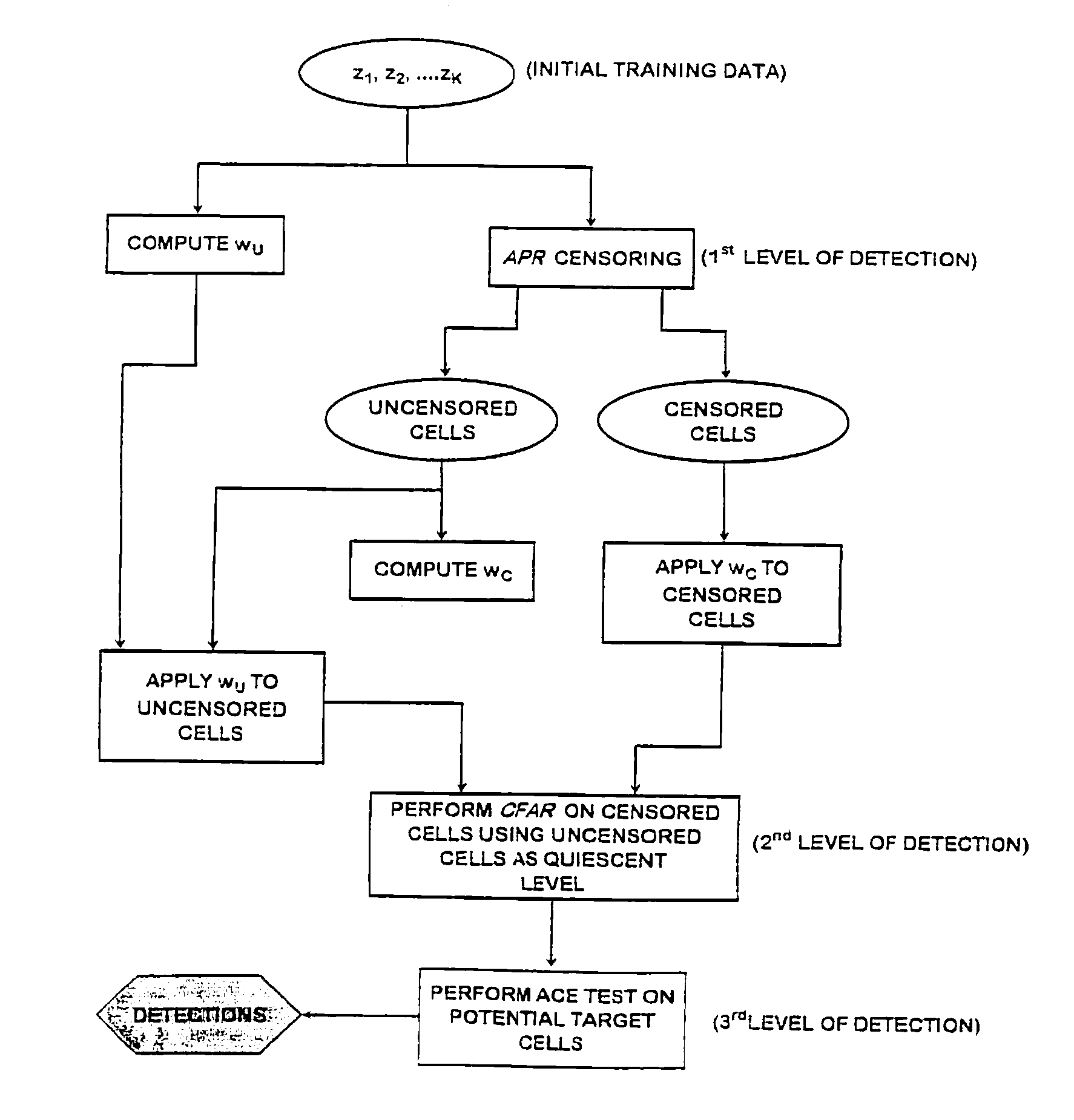
An adaptive radar processing system includes an antenna array for transmitting a radar signal and for receiving a return radar signal, and a signal processor programmed with an enhanced FRACTA algorithm (FRACTA.E). The basic FRACTA algorithm is enhanced to FRACTA.E with (any or all of) five enhancements, versions 1-5. Version 1 is a stopping criterion, for censoring samples, that is adaptive to a radar return data set. The inclusion of a stopping criterion improves the computational speed of FRACTA.E thereby improving its efficiency. Version 2 uses global censoring. Version 3 uses fast reiterative censoring. Version 4 uses segmenting of data vectors for AMF application. Version 5 uses Knowledge-aided covariance estimation (KACE) to reduce the required sample support that may be necessary in non-homogeneous environments, providing substantially the same level of detection performance with considerably less training data.

Description

[0001] The present application claims the benefit of the priority filing date of provisional patent application Ser. No. 60 / 499,373, filed Sep. 3, 2003, incorporated herein by reference.FIELD OF THE INVENTION [0002] This invention relates to a processing method and system for radar applications. More particularly, the invention relates to adaptive radar processing. BACKGROUND OF THE INVENTION [0003] Radar systems such as those used for airborne applications typically have to contend with the presence of non-homogeneous clutter, jamming, and dense target clusters. An approach that has proved successful in minimizing the masking effect of undesirable false signals on a target return signal is adaptive matched filtering for signal processing. [0004] Adaptive signal processing systems have many applications including radar reception, cellular telephones, communications systems, and biomedical imaging. Adaptive signal processing systems utilize adaptive filtering to differentiate between...

Claims


Application Information

Patent Timeline
Patent Type & Authority Applications(United States)
IPC IPC(8): G01S13/88
CPCG01S7/295G01S13/5246
Inventor GERLACH, KARL R.BLUNT, SHANNON D.
Owner THE UNITED STATES OF AMERICA AS REPRESENTED BY THE SECRETARY OF THE NAVY
Learn More