Display backlight with improved light coupling and mixing

a technology of backlight and assembly, which is applied in the field of display backlight assembly, can solve the problems of light entering the light guide from the edges, assembly is typically fragile, and contains environmentally hazardous materials, so as to improve the management of light emitted, improve the coupling and mixing, and eliminate the effect of air gap

Active Publication Date: 2007-04-12
LIGHTING SCI GROUP
View PDF34 Cites 197 Cited by
  • Summary
  • Abstract
  • Description
  • Claims
  • Application Information

AI Technical Summary

Benefits of technology

[0010] The present invention relates to an edge-lit display backlight assembly that improves the coupling and mixing of multi-colored and/or mono-chromatic light produced by a solid state light source. According to an embodiment of the present invention, the display backlight assembly includes a display optical light guide (DOLG) and a solid state light source (SSLS) coupled together by an optical coupler. As u

Problems solved by technology

However, not all of the light that enters the light guide from the edges is emitted uniformly from the light guide surface that is opposite the reflector.
As such, conventional CCFL display backlight assemblies, such as the one shown in FIG. 1, are limited by a number of drawbacks.
For example, these assemblies are typically fragile and contain environmentally hazardous material, such as mercury.
Furthermore, conventional CCFL display backlight assemblies fail to produce a full spectrum of light.
In addition, the assemblies cannot be rapidly switched to reduce frame jitter.
Disadvantageously, many typical display backlight assemblies include a physical gap between the CCFL and the light guide.
Generally, the physical gap is maintained between the two elements because the fluores

Method used


Image

  • Display backlight with improved light coupling and mixing
  • Display backlight with improved light coupling and mixing
  • Display backlight with improved light coupling and mixing

Examples


Embodiment Construction

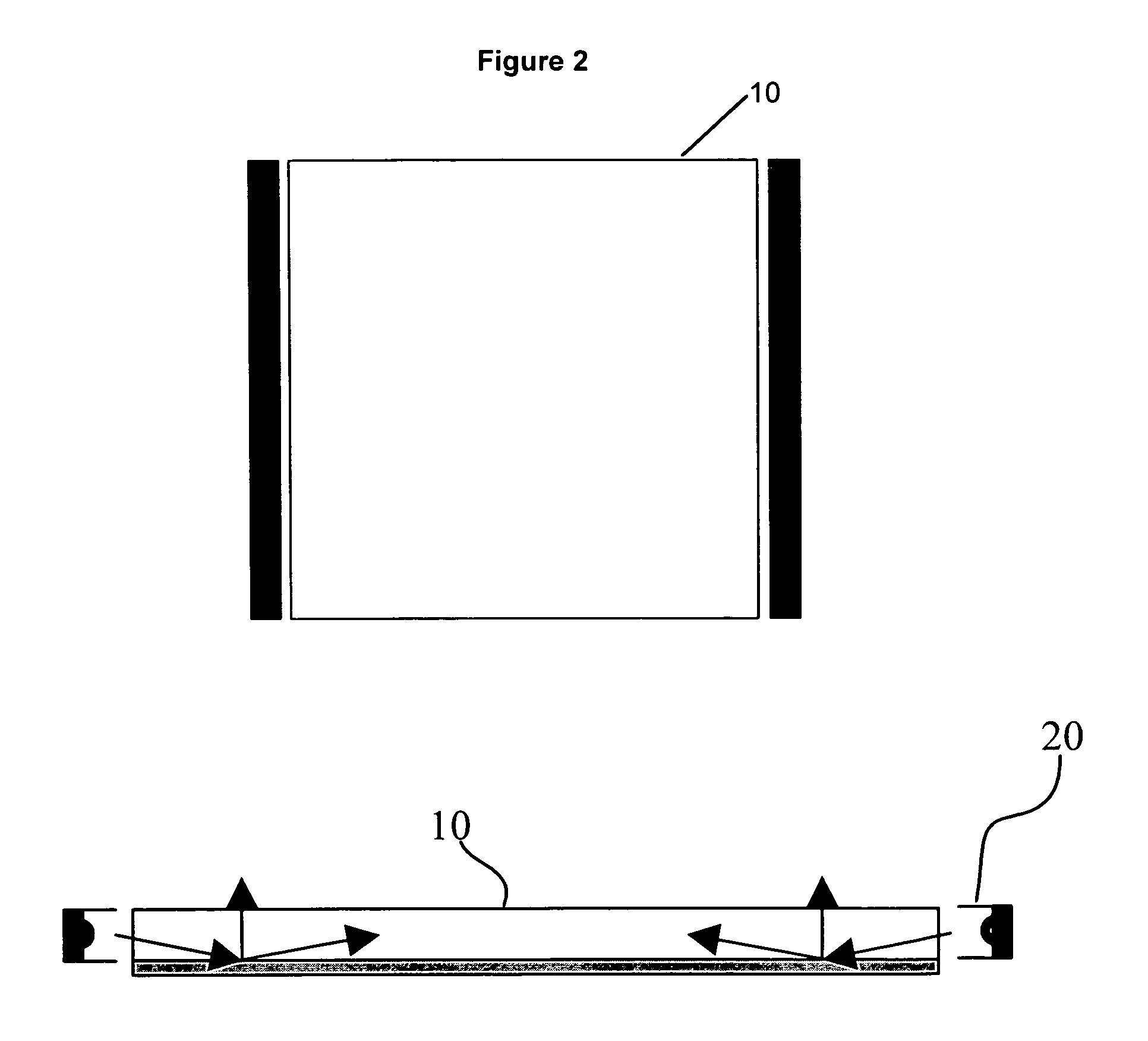
[0027]FIG. 2 shows an exemplary display backlight assembly using a solid state light source (SSLS) 20, according to an embodiment of the present invention. The SSLS 20 according to the embodiment shown in FIG. 2 may include any suitable solid state light source, such as, for example, light emitting diodes (LEDs), solid state lasers, or other suitable semi-conductor-based light source. Furthermore, the SSLS 20 may include one or more resonant cavity light emitting diodes (RCLED), one or more super luminescent light emitting diodes (SLEDs), or one or more organic LEDs. One having ordinary skill in the art will appreciate that the SSLS 20 may include multiple devices (i.e., multiple LEDs) and may include devices that emit light at multiple wavelengths (i.e., a multi-colored array of LEDs). For example, a LED-based SSLS 20 may include an array of red LEDs (labeled as “R” in FIGS. 3-6), green LEDs (labeled as “G” in FIGS. 3-6), and blue LEDs (labeled as “B” in FIGS. 3-6).

[0028]FIG. 3 sh...


PUM


Abstract

A display backlight assembly providing improved optical coupling between a solid state light source and a display optical light guide. The assembly includes an optical coupler to couple the solid state light source and display optical light guide together. In addition, the optical coupler may include a light mixing element for improved mixing of the multi-colored or mono-chromatic light produced by the solid state light source.

Description

CROSS REFERENCE TO RELATED APPLICATION [0001] This application claims the benefit of U.S. Provisional Application Ser. No. 60 / 694,740, filed on Jun. 28, 2005. The entire disclosure of U.S. Provisional Application Ser. No. 60 / 694,740 is incorporated by reference herein.FIELD OF THE INVENTION [0002] The present invention relates to a display backlight assembly providing improved coupling and color mixing. More specifically, the present invention relates to a device providing improved coupling and mixing of multi-colored and mono-chromatic light produced by one or more solid state light sources, such as, for example, light emitting diodes (LEDs), such as a resonant cavity light emitting diodes (RCLEDs), super luminescent light emitting diodes (SLEDs), or organic LEDs. BACKGROUND OF THE INVENTION [0003] Display technology used in many television and computer applications typically uses a backlight panel or plate for illumination of a display, particularly a liquid crystal display (LCD)....

Claims


Application Information

Patent Timeline
IPC IPC(8): F21V7/04
CPCG02B6/0021G02B6/0028G02B6/0068
Inventor BAILEY, EDWARDMAZZOCHETTE, JOSEPH B.BEREGSZASZI, ANDREWBURDALSKI, ROBERT J.
Owner LIGHTING SCI GROUP
Why Eureka
Try Eureka