Optical connection structure and optical connection method

a technology of optical connection and optical fiber, applied in the field of optical connection structure, can solve the problems of increased connection loss, brittleness and weakness of optical fiber, and a large amount of time and cost for grinding, and achieves the effect of improving the ease of handling, no negative effects, and simple overall structur

Active Publication Date: 2007-04-19
TOMOEGAWA PAPER CO LTD
View PDF3 Cites 60 Cited by
  • Summary
  • Abstract
  • Description
  • Claims
  • Application Information

AI Technical Summary

Benefits of technology

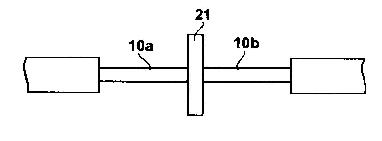
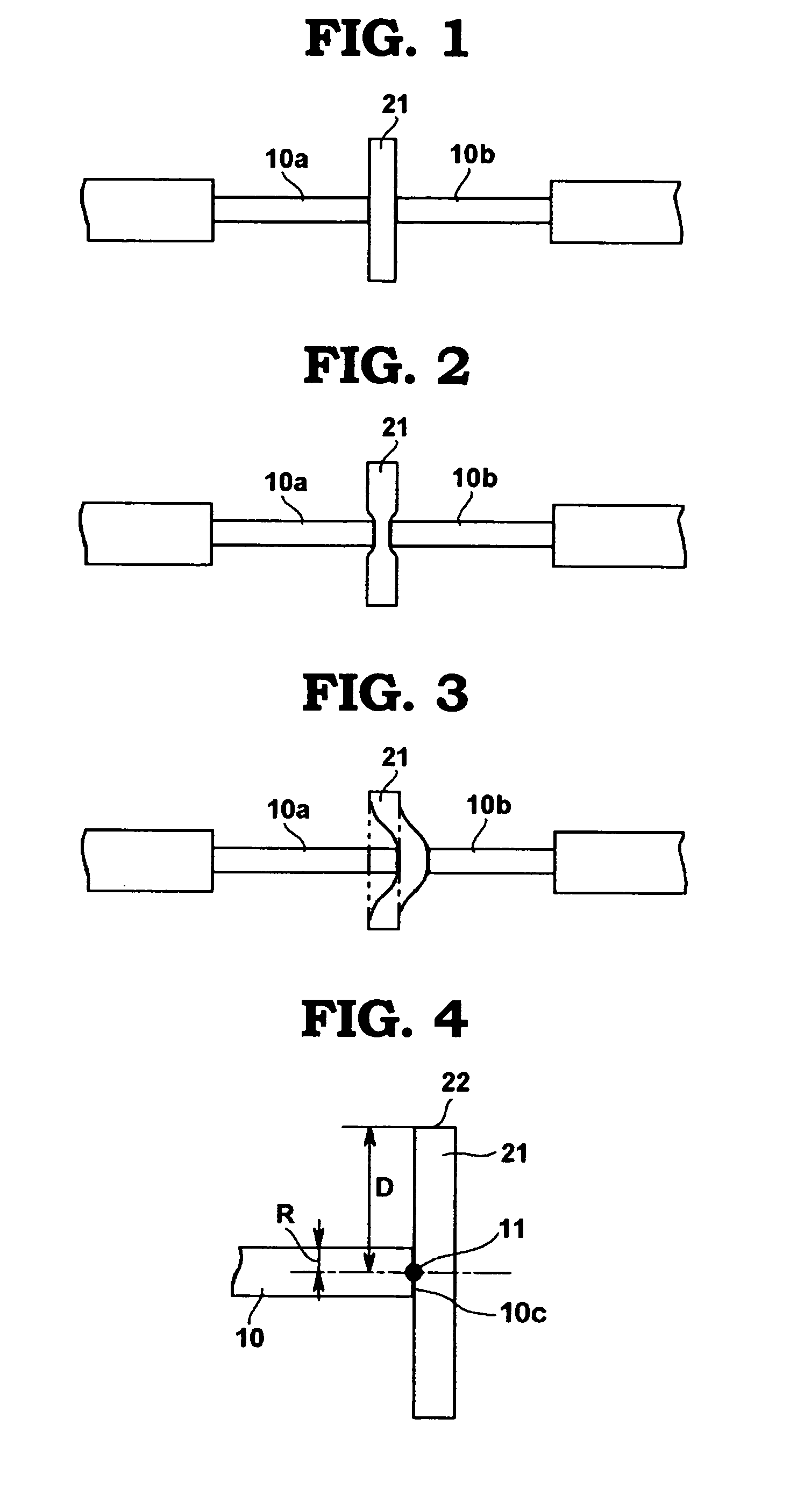
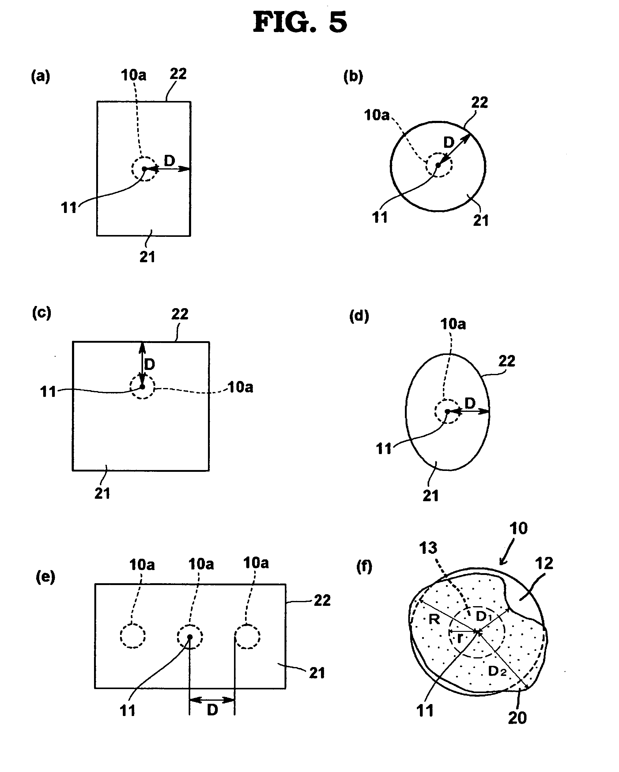
[0043] In the optical connection structure proposed by the present invention, the solid viscous connection member has a single-layer structure. Therefore, the overall structure is simple and does not cause reflection of light. Also, the viscous connection member does not allow the refractive-index matching agent to enter the cavity in a holey fiber, which often occurs when the refractive-index matching agent is liquid, and thus this structure has no negative effects at all on the optical fiber transmission characteristics. Since the viscous connection member is solid, it does not cause contamination by flowing out into the area around the connection point. This prevents attachment of dust and improves the ease of handling. Moreover, the viscous connection member can be adhered only to the end face of an optical transmission medium, which means the surroundings are not contaminated while the connection point is not contaminated by the surroundings, either. Furthermore, the solid viscous connection member attaches to the end face of an optical transmission media by means of contact, and thus there is no need to provide a separate, special supporting means or structure to retain the viscous connection member. As a result, the viscous connection member can be supported by a simple supporting member, which contributes to space saving. Being solid, the viscous connection member can also freely change its shape in between the media, which prevents air from entering the space between the ends of optical transmission media and permits connection of low optical transmission loss without having to add a grinding process. Additionally, the restoration property of the viscous connection member permits

Problems solved by technology

In the case of connection using an optical connector, generally optical fibers are inserted into ferrules for protection when achieving physical contact between the end faces of optical fibers, because optical fibers are brittle and weak.
If the angles of end faces are offset or end faces are rough, for example, air enters between the butted ends of optical fibers and increases Fresnel reflection at connected end faces, which results in increased connection loss.
However, grinding requires a lot of time and cost and is not suitable for general connection applications.
Therefore, how to improve the aforementioned problem still remains a great challenge.
However, this method presents a problem because silicone or paraffin-based liquid or grease refractive-index matching agents are used in general, and applying a specified amount of these refractive-index matching agents on the end face of an optical fiber, which provides only a small area, is difficult.
If an excessive amount of refractive-index matching agent is applied, the area around the connection point is contaminated and dust and other foreign particles are attached.
Also, refractive-index matching agents used in this method generally have high flowability, and therefore they easily flow out of the connection point, which makes it difficult to obtain optical stability.
This requires considerable time and reduces work efficiency.
However, the former structure presents difficulty adjusting the pressure force applied on the optical fiber to adhere the alignment material film, and application of excessive pressure can cause the optical fiber to crack or chip.
In the latter structures, the elasticity of the elastic body alone cannot achieve sufficient adhesion, and excessive pressure may be applied

Method used


Image

  • Optical connection structure and optical connection method
  • Optical connection structure and optical connection method
  • Optical connection structure and optical connection method

Examples


example 1

[0150] Using sheet-shaped viscous connection member (1) obtained above, an optical connection structure was formed as shown in FIG. 33. First, the V-groove cross-sections of two V-grooved alignment members 43a, 43b (5 mm×10 mm in size) were positioned using an optical microscope. Then, the ends of V-grooves were aligned at a position 0.2 mm from a 0.05-mm slit 801 provided in a glass board 80, and the alignment members were affixed on the glass board 80 using adhesive. Thereafter, the above sheet-shaped viscous connection member 21 was inserted into the slit in the glass board and placed vertically to the surface of the glass board. Then, optical fibers 10a, 10b were placed inside the V-grooves in both alignment members 43a, 43b. Optical fibers were quartz optical fibers (single-mode fiber of 250 μm in diameter, manufactured by Furukawa Electric), each of which had been stripped by 25 mm from the end using a fiber stripper to expose the optical fiber element wire, which had then bee...

example 2

[0153] Using sheet-shaped viscous connection member (2) obtained above, an optical connection structure was formed in the same manner as in Example 1. When the connection loss of the connected optical fibers was measured, the reading was 0.4 dB or below, indicating good optical characteristics. In addition, a heat resistance test (in conformance with JIS C 0021) was conducted with the optical connection structure left standing in an environment of 125±2° C., along with a temperature cycle test for 500 cycles in a temperature range of −40° C. to 75° C. As a result, the changes in optical transmission loss were 0.4 dB or below. When the viscous connection member was observed after removing the optical connection, no solidification or yellowing was found, showing that the optical connection component was sufficiently reusable.

example 3

[0154]FIG. 34 is a plan view showing an optical connection structure that connects four-core optical fiber tapes. To achieve optical connection of four optical fibers on each side, connection operation was performed in the same manner as in Example 1, except that two four-core optical fiber tapes 15a (this fiber tape contains optical fibers 101-104), 15b and two V-grooved alignment members 43a, 43b affixed on a glass board 80 were used. As a result, four optical fibers could be easily connected optically using one sheet-shaped viscous connection member 21. When the lengths of cut optical fibers were measured, there was a variation of approx. ±10 μm among the four optical fiber element wires. Since the sheet-shaped viscous connection member deformed flexibly to adhere to and affix each optical fiber, however, the variation in optical transmission loss among the optical fiber element wires was small. Specifically, the changes in optical transmission loss over 100 detachment / reattachme...


PUM


Abstract

There are provided an optical connection structure and an optical connection method capable of holding an optical fiber in a close contact state with a simple structure and easily mounting and detaching the optical fiber while enabling connection having an excellent optical stability. The optical connection structure includes a solid-state adhesive connection member having a refraction factor conformance as a single layer sandwiched between end surfaces of opposing optical transmission media or between the optical transmission media and the optical part. It is preferable that the solid-state adhesive connection member be formed by silicone resin or acryl resin.

Description

TECHNICAL FIELD [0001] The present invention relates to an optical connection structure that connects an optical transmission medium with another optical connection medium or optical component, as well as an optical connection method for forming the same. BACKGROUND ART [0002] The most common method to connect optical fibers is by means of physical connection, whereby optical fibers or ferrules in which optical fibers are inserted are butted against each other and thereby connected. Examples of connection components that utilize such physical connection include mechanical splices and optical connectors. In general, mechanical splices are effective when components are connected permanently, while optical connectors are effective when connected components are detached and reattached frequently. Both are widely utilized in their respective applications. Both mechanical splices and optical connectors effect physical connection by applying pressure on the end faces of optical fibers in t...

Claims


Application Information

Patent Timeline
IPC IPC(8): G02B6/38G02B6/255G02B6/26
CPCG02B6/255G02B6/3636G02B6/3652G02B6/382G02B6/3877G02B6/26G02B6/38
Inventor SUZUKI, MASAYOSHISASAKI, KYOICHIKOBAYASHI, TATSUSHI
Owner TOMOEGAWA PAPER CO LTD
Why Eureka
Try Eureka