Highly durable polarization plate and liquid crystal display

Inactive Publication Date: 2007-04-26
SUMITOMO CHEM CO LTD
View PDF6 Cites 24 Cited by
  • Summary
  • Abstract
  • Description
  • Claims
  • Application Information

AI Technical Summary

Benefits of technology

[0024] The polarizer of the invention has an excellent ability to block moisture, this allows the polarizer to retain its optical qualities under wet-heat environments, and, by controlling water content in the polarizer, to avoid deterioration in its appearance such as generation of wrinkled defects even under dried and high temperature environments. Consequently, the polarizer is suitably used for liquid crystal di

Problems solved by technology

Disposing any of such protective films having low water-vapor permeability to at least one side or particularly the outmost side of a polyvinyl alcohol polarizing film, this exhibits an excellent durability under a wet-heat environment; however, if this is exposed under a high temperature environment with low humidity, this causes deterioration in its appearance such as generation of wrinkled surface defects, resulting in problems such as adverse effects on displaying ability of liquid crystal displays.
For example, Japanese Patent No. 2000-321428A (Patent Literature 7) notes that, when a polarizer is disposed with an antireflection layer on a surface of a protective film thereof, a heat resistance thereof often becomes insufficient, and that this is caused by the reduction of the water-vapor permeability due to disposing the antireflection layer, therefore, in this literature, provides a polarizer having a water-vapor permeability of 10 g/m2·24 hours or more even thou

Method used


Image

  • Highly durable polarization plate and liquid crystal display
  • Highly durable polarization plate and liquid crystal display
  • Highly durable polarization plate and liquid crystal display

Examples


example 1

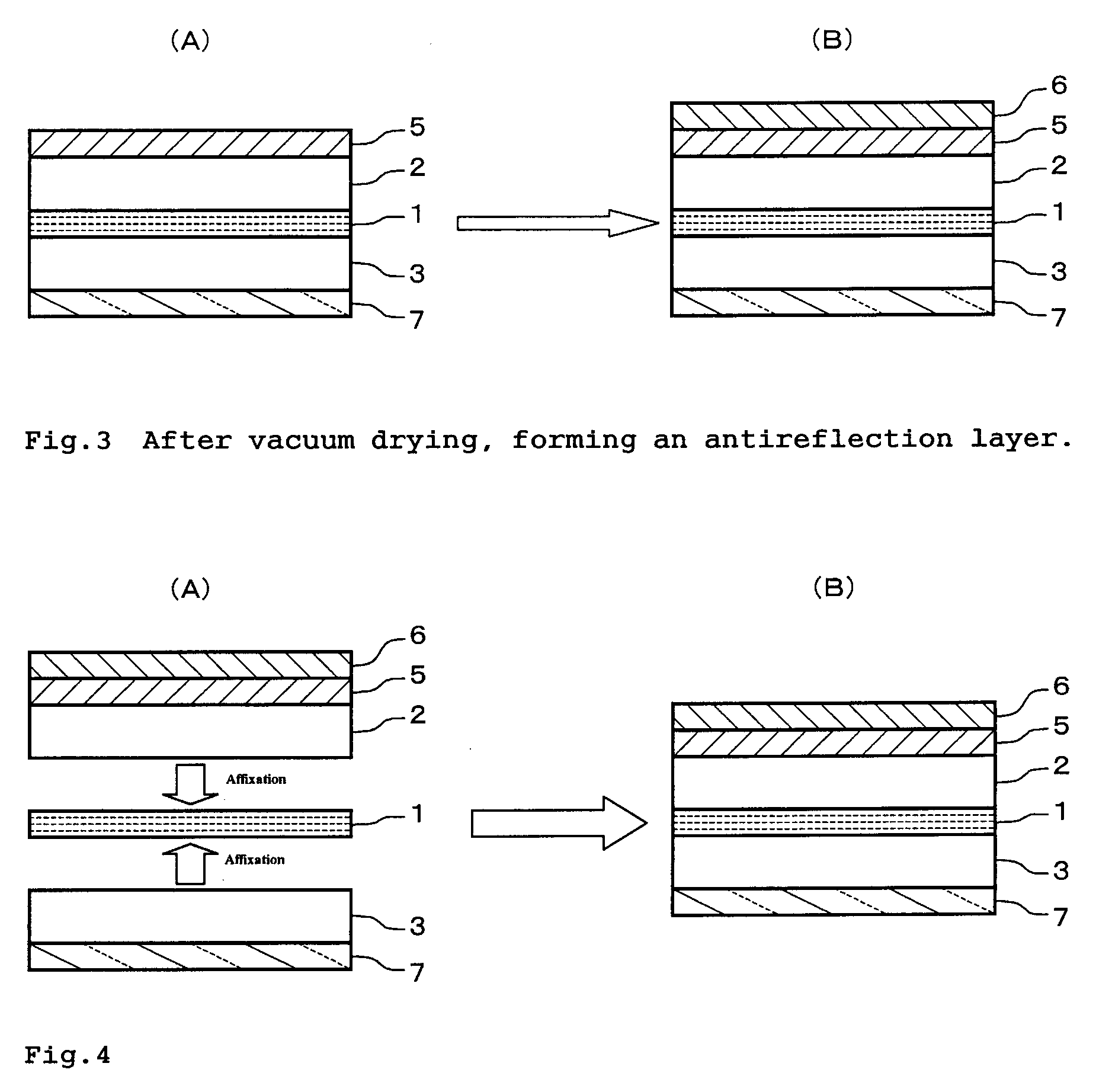
[0075] As shown in FIG. 3(A), a polarizer was produced by interposing a polarizing film 1 composed of an oriented film of iodine dye-polyvinyl alcohol between two transparent protective films 2 and 3 composed of triacetylcellulose. The first transparent protective film disposed on one side of the polarizing film 1 was a film providing a hard coated layer 5 produced by TOPPAN PRINTING CO., LTD. on one side of a triacetylcellulose film 2; the second transparent protective film disposed on the other side of the polarizing film 1 was a film providing an optical compensation layer 7 composed of an oriented coating layer of a discotic liquid crystal on one side of a triacetylcellulose film 3 via polyvinyl alcohol oriented film (not shown), which is produced by Fuji Photo Film Co., Ltd. with the trade name of “WV-SA”; and each of the protective films was affixed to the polarizing film 1 respectively with the side of triacetylcellulose films 2 or 3 thereof via an adhesive. The thickness of ...

example 3

[0095] The polarizer with pressure-sensitive adhesive layer which was produced in Example 2 was cut into chips with about 8 inches (200 mm) width across corner in the manner that the absorption axis of the chip was in an angle of 45 degree in anti-clockwise rotation with respect to the long side thereof, the chip cut was affixed to a glass plate having 1.1 mm thickness with the side of the pressure-sensitive adhesive layer thereof to form a sample; thereafter, this sample was pressed with conditions at 50° C. under 5 atmospheric pressure for 20 minutes, and then left for 24 hours. Thereafter, the sample was put in a high temperature and humidity oven conditioned at 65° C. with a relative humidity of 90%, followed by taken out from the oven after 65 hours elapsed to be subjected to an appearance observation, thereby generation of defects such as peeling or blistering was not found on the sample.


PUM


Abstract

The present invention provides a polarizer comprising a polarizing film, a first transparent protective film and a second transparent protective film, the polarizing film being between the first transparent protective film and the second transparent protective film, wherein the first transparent protective film has a water-vapor permeability of 50 g/m2·24 hours or less at 40° C. under a relative humidity of 90 % and a water content of the polarizer is 2.0% by weight or less.

Description

FIELD OF THE INVENTION [0001] The present invention relates to polarizers with excellent durability for liquid crystal displays. The invention also relates to liquid crystal displays using the polarizers. BACKGROUND OF THE INVENTION [0002] Recently, liquid crystal displays are commonly used for automobiles and cellular phones, and are required reliability under such environments as to be high temperature or high temperature and humidity. In particular, when they are used for automobiles, durability under very severe conditions is desired such that no deterioration is caused in their performance even under exposure of a high temperature in summer. [0003] Liquid crystal displays are generally constructed as follows; placing two electrode substrates having a transparent electrode in an arrangement of their transparent electrodes facing to each other, inserting a liquid crystal therebetween to form a liquid crystal cell, and then affixing a polarizer on the one or both faces of the liqu...

Claims


Application Information

Patent Timeline
IPC IPC(8): C09K19/00
CPCG02B1/105Y10T428/1036G02F1/133528G02B1/14C09K2323/03G02B5/30G02F1/1335
Inventor MATSUNO, KENJIINOUE, TOSHIYA
Owner SUMITOMO CHEM CO LTD
Why Eureka
Try Eureka