Apparatus and method for thin film deposition

a thin film and apparatus technology, applied in the direction of chemically reactive gases, coatings, crystal growth processes, etc., can solve the problems of reducing the productivity of mass production, affecting the thermodynamic stability of atoms, and affecting the production efficiency of atoms

Active Publication Date: 2007-05-03
KOOKJE ELECTRIC KOREA
View PDF19 Cites 309 Cited by
  • Summary
  • Abstract
  • Description
  • Claims
  • Application Information

AI Technical Summary

Benefits of technology

[0022] Accordingly, the present invention has been made to solve the above-described problems occurring in the prior art, and it is an object of the present invention to provide an apparatus for and a method of depositing a thin film, in which, dissimilar to a conventional technology where a gas supply and exhaust are repeated through the operation of a valve and

Problems solved by technology

However, the reactions occur fast and thus it is very difficult to control the thermodynamic stability of atoms.
In addition, the time for an appropriate amount of gas to reach the substrate 3 is delayed, due to the valve driving electrical signal associated with the valve operation, a time delay caused during air driving, and conductance generated in the narrow gas tubes.
In addition, since the reaction chamber 1 has a small volume for the purpose of speedy replacement of gas in the reaction chamber 1, the number of the substrate 3 capable of being mounted in the reaction chamber 1 is limited, thus leading to a decreased productivity in mass production.
In this case, problematically, the speed of the reaction gas reaching the substrate 3 is not coincident with the electrical transmission speed of th

Method used


Image

  • Apparatus and method for thin film deposition
  • Apparatus and method for thin film deposition
  • Apparatus and method for thin film deposition

Examples


Embodiment Construction

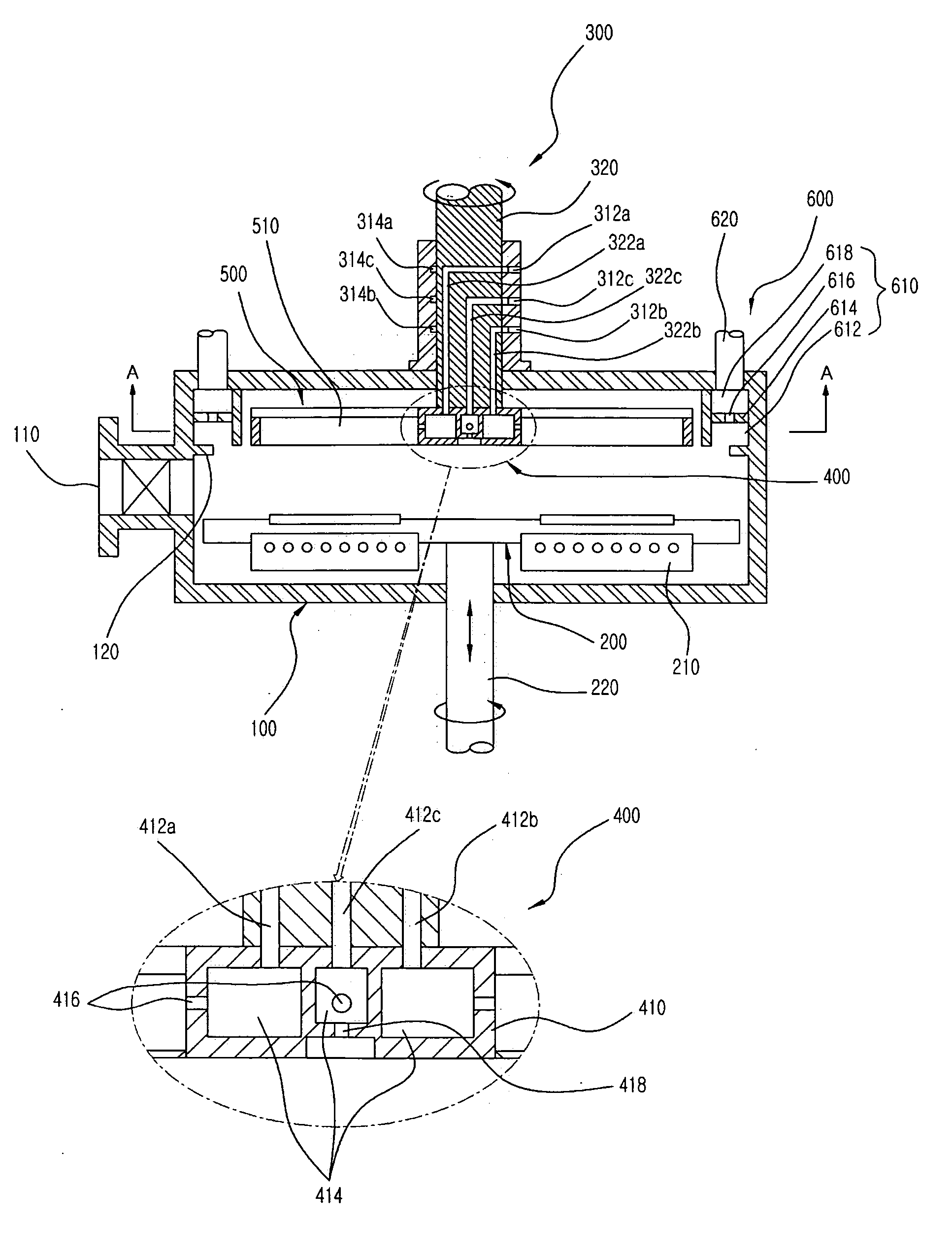
[0043] The preferred embodiments of the invention will be hereafter described in detail, with reference to the accompanying drawings.

[0044]FIG. 5 is a schematic sectional view of a thin film deposition apparatus employing a rotary reaction cell mode and a layer behavior mode according to an embodiment of the invention. As illustrated in FIG. 5, a substrate entrance and exit 110 is formed at a side of a reaction chamber 100, and a heater 210 for heating a substrate is installed in a susceptor, on which a plurality of substrates supplied through the substrate entrance and exit 110 is rested. The susceptor having the above construction ascends and descents, and rotates by means of a susceptor rotation shaft 220, which is connected to the lower portion of the susceptor 200 in order to load and unload a substrate. This construction is well known, and thereinafter new features of the invention will be described in detail.

[0045] First, referring to FIG. 5, a gas supply means 300 is provi...


PUM

PropertyMeasurementUnit
Lengthaaaaaaaaaa
Angular velocityaaaaaaaaaa
Lengthaaaaaaaaaa

Abstract

Disclosed herein is a thin film deposition apparatus having a reaction chamber for forming a thin film on a plurality of substrates rested on a susceptor. The apparatus comprises: a gas supply means for supplying a plurality of gases to the inside of the reaction chamber from the outside, the gases including a reaction gas; a gas distribution means for distributing and spraying the gases supplied from the gas supply means so as to conform to the purpose of a process; a gas retaining means having a plurality of reaction cells for partitionally accommodating and retaining the respective gases distributed from the gas distribution means; a rotation driving means for rotating the gas retaining means such that the gases retained in the respective reaction cells are exposed to the substrates in sequence; and a gas exhaust means for pumping the gases retained by the gas retaining means to the outside of the reaction chamber.

Description

BACKGROUND OF THE INVENTION [0001] 1. Field of the Invention [0002] The present invention relates to an apparatus for and a method of depositing a thin film, and more particularly to an apparatus for and a method of depositing a thin film, in which, dissimilar to a conventional technology where a gas supply and exhaust are repeated through the operation of a valve and a pump installed in a reaction chamber, a gas is continuously supplied to the inside of the reaction chamber, and the supplied gas is exposed to respective substrates through a plurality of separate reaction cells and simultaneously excessive gases are continuously exhausted, thereby improving reaction rate and characteristics. BACKGROUND OF THE RELATED ART [0003] In general, semiconductor manufacturing processes employ a sputtering, chemical vapor deposition, atomic layer deposition method to thereby form a uniform thin film. [0004] Among these thin film deposition methods, the chemical vapor deposition method has bee...

Claims


Application Information

Patent Timeline
IPC IPC(8): C23C16/00
CPCC23C16/4412C23C16/45551C23C16/45574C23C16/45589C23C16/509C30B25/14H01J2237/332H01L21/20
Inventor BAEK, YONG-KULEE, SEUNG-HOON
Owner KOOKJE ELECTRIC KOREA
Why Eureka
Try Eureka