
Photovoltaic concentrating apparatus

a technology of concentrating apparatus and photovoltaic energy, applied in lighting and heating apparatus, light radiation electric generators, generators/motors, etc., can solve the problems of inability to be widely used, lack of flexibility for design changes, heavy and inconvenient assembly, etc., and achieve low manufacturing cost and flexibility for changing architecture.

Inactive Publication Date: 2007-05-03
INST NUCLEAR ENERGY RES ROCAEC
View PDF10 Cites 18 Cited by
  • Summary
  • Abstract
  • Description
  • Claims
  • Application Information

AI Technical Summary

Benefits of technology

[0007] The objective of the present invention is to provide a photovoltaic concentrating apparatus, which possesses flexibility for changing architecture and low manufacturing cost.
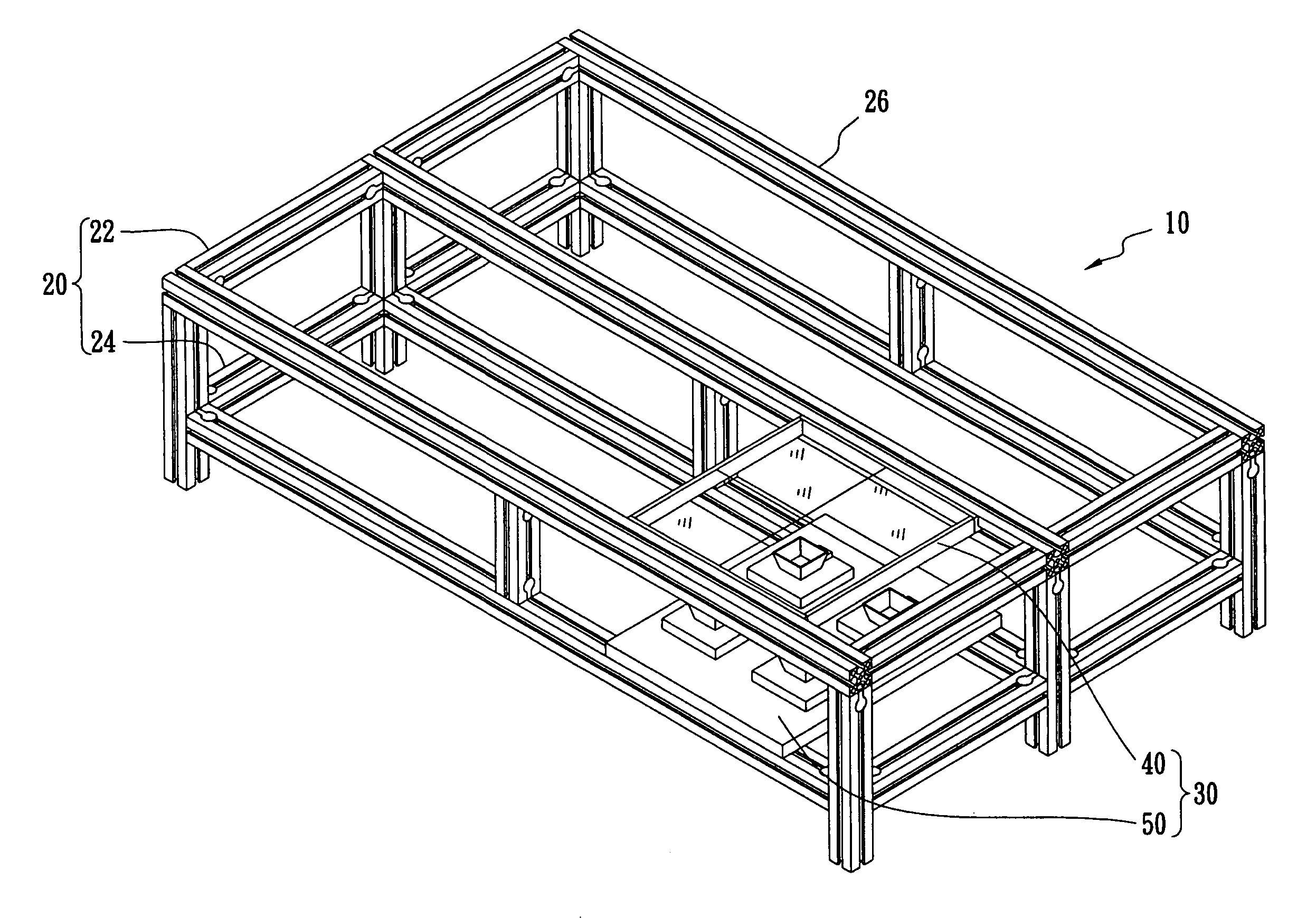
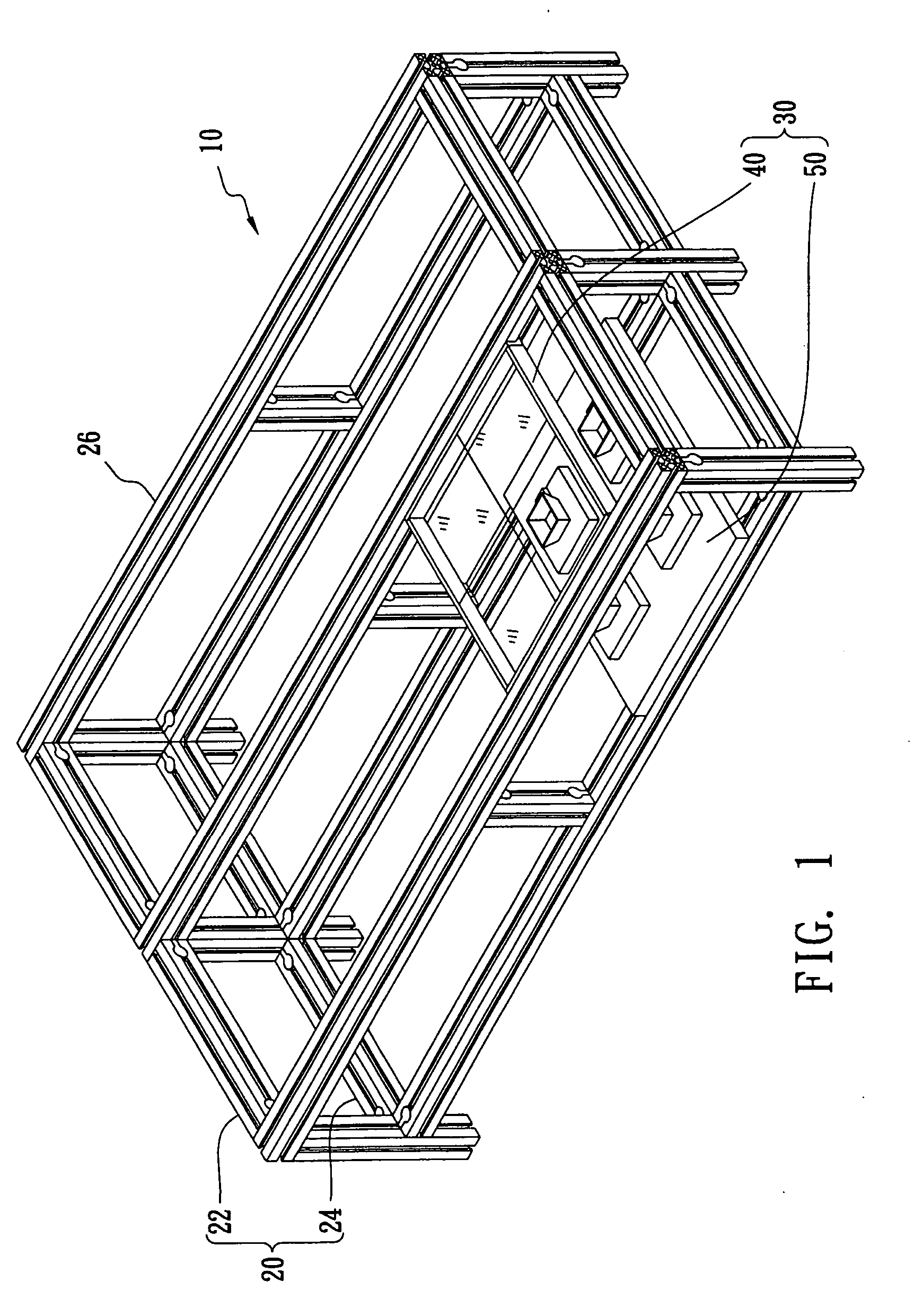
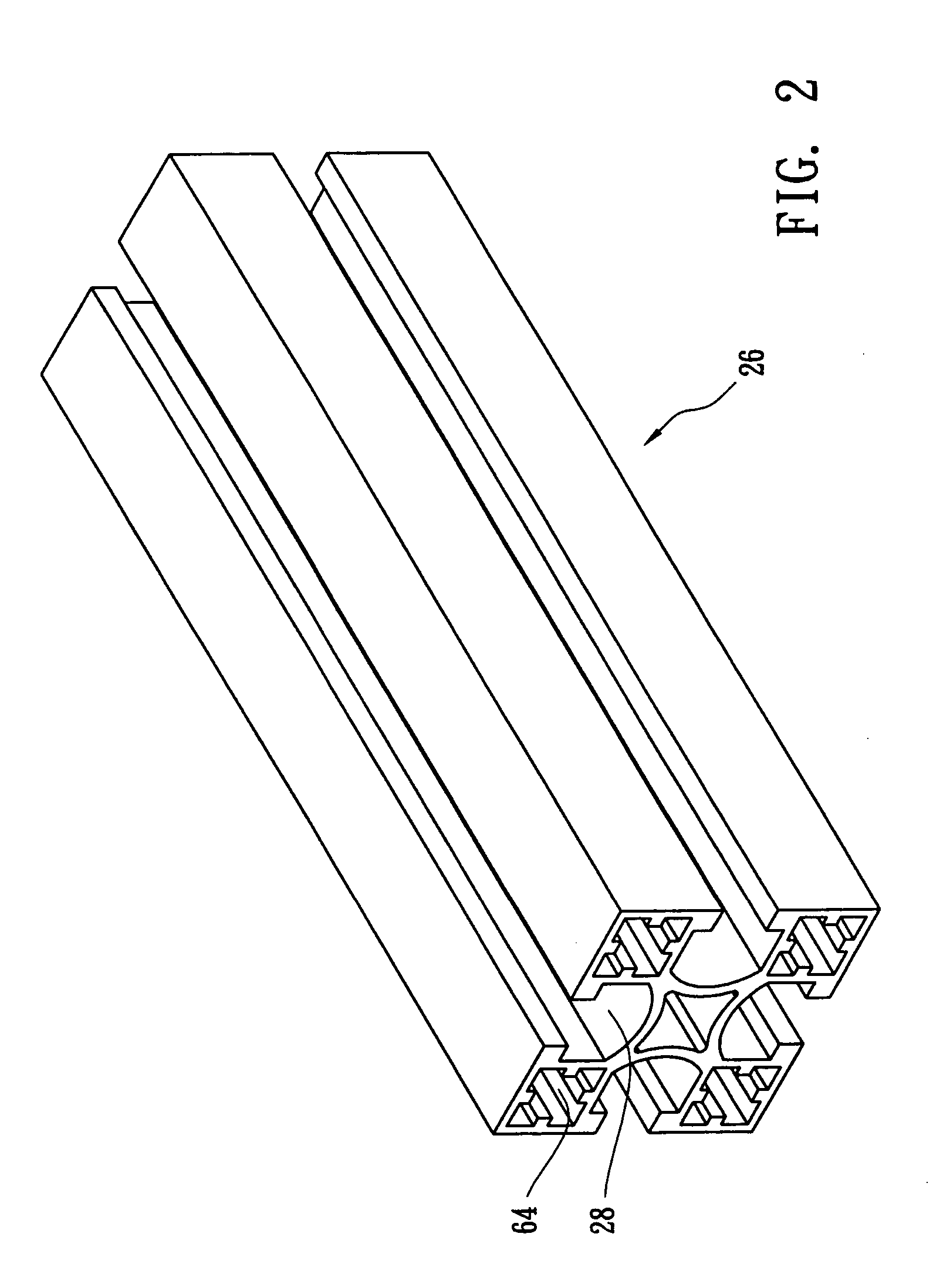
[0009] The solar cell module comprises a dielectric substrate positioned on the plate, a solar cell positioned on the upper surface of the dielectric substrate, a protection diode positioned on the upper surface of the dielectric substrate, a condenser configured to condense light beams from the Fresnel lens to the solar cell, and a heat sink positioned on the back surface of the dielectric substrate. Preferably, the supporter is made of aluminum or aluminum-containing alloy and the beam includes at least one hollow interior to reduce the weight of the supporter. In addition, the surface of the supporter is preferably blasted, anodized, or electroplated.
[0011] The prior art uses frames made of glass, which is too heavy to be assembled conveniently and lacks flexibility for design changes. Conversely, the present supporter is preferably made of aluminum or aluminum-containing alloy and the beam includes at least one hollow interior, and therefore can decrease the weight of the photovoltaic concentrating apparatus dramatically. In addition, the beam of the supporter is grooved, which allows the Fresnel lens and the solar cell module to be assembled at a random position on the beam, and therefore a designer or user can randomly change the number and position of the Fresnel lens and the solar cell module, i.e. the present photovoltaic concentrating apparatus possesses flexibility for changing architecture randomly.

Problems solved by technology

Particularly, each element of the collecting unit is made of glass, which is heavy and inconvenient to assemble.
In short, the solar energy collecting module disclosed by A. W. Bett et al. is too heavy for easy assembly, lacks flexibility for design changes, and therefore cannot be widely used.

Method used


Image

  • Photovoltaic concentrating apparatus
  • Photovoltaic concentrating apparatus
  • Photovoltaic concentrating apparatus

Examples


Embodiment Construction

[0015]FIG. 1 to FIG. 4 illustrate a photovoltaic concentrating apparatus 10 according to one embodiment of the present invention. The photovoltaic concentrating apparatus 10 comprises a supporter 20 and at least one collecting unit 30 positioned on the supporter 20. The collecting unit 30 includes a Fresnel lens 40 positioned on the supporter 20 via a loading frame 42 and a solar cell module 50 positioned on the supporter 20 via a plate 52, wherein the loading frame 42 comprises a wing 44 which can be inserted into the groove 28 of the beam 26. Particularly, the supporter 20 comprises an upper frame 22 for supporting the Fresnel lens 40 and a bottom frame 24 for supporting the solar cell module 50. The supporter 20 includes a plurality of beams 26 having at least one groove 28 positioned on a side surface of the beam 26. Preferably, the supporter 20 is made of aluminum or aluminum-containing alloy and the beam 26 includes at least one hollow interior 64 to reduce weight, as shown in...


PUM


Abstract

The photovoltaic concentrating apparatus includes a supporter and at least one collecting unit positioned on the supporter. The supporter includes a plurality of beams having at least one groove positioned on a side surface of the beam. The collecting unit includes a Fresnel lens and a solar cell module. The Fresnel lens is positioned on the supporter via a loading frame with a wing capable of engaging with the groove of the beam, and the solar cell module is positioned on the supporter via a substrate. Particularly, the supporter includes an upper frame for supporting the Fresnel lens and a bottom frame for supporting the solar cell module.

Description

RELATED U.S. APPLICATIONS [0001] Not applicable. STATEMENT REGARDING FEDERALLY SPONSORED RESEARCH OR DEVELOPMENT [0002] Not applicable. REFERENCE TO MICROFICHE APPENDIX [0003] Not applicable. FIELD OF THE INVENTION [0004] The present invention relates to a photovoltaic concentrating apparatus, and more particularly, to a photovoltaic concentrating apparatus, which possesses flexibility for changing architecture and low manufacturing cost. BACKGROUND OF THE INVENTION [0005] As industry is experiencing rapid growth, petroleum exhaust and the discharge of greenhouse gases from the use of petroleum are drawing more and more attention. Nowadays, researchers try to find alternative energy sources to achieve a stable energy supply. One such alternative energy source is solar cells, which use the photoelectric effect to transform solar energy into electrical energy without generating polluting gases or greenhouse gases such as those produced by conventional energy sources. Particularly, sol...

Claims


Application Information

Patent Timeline
IPC IPC(8): H02N6/00F24S23/00
CPCY02E10/52H01L31/0547H01L31/0543
Inventor SHIN, HWA YUHHONG, HWEN FENCHENG, CHIEHCHIU, HUNG SHENGTZENG, YEN CHENG
Owner INST NUCLEAR ENERGY RES ROCAEC
Learn More