
Nitride Semiconductor Wafer

a technology of nitride and semiconductor wafers, applied in the direction of silicates, silicon compounds, crystal growth processes, etc., can solve the problems of insufficient optical, electrical and mechanical properties, and not a simple matter, and achieve excellent properties and high quality

Active Publication Date: 2007-05-03
SUMITOMO ELECTRIC IND LTD
View PDF0 Cites 0 Cited by
  • Summary
  • Abstract
  • Description
  • Claims
  • Application Information

AI Technical Summary

Benefits of technology

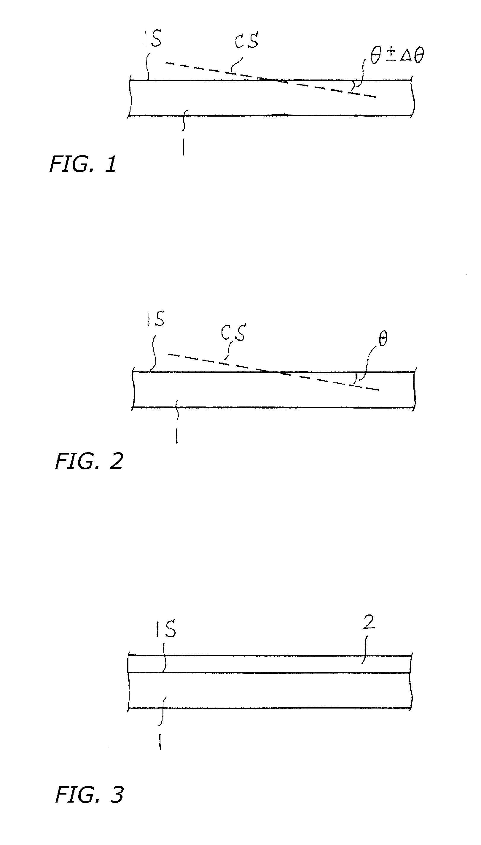
[0018] According to the present invention, it is possible to provide a nitride semiconductor substrate having properties preferable for the manufacture of various nitride semiconductor devices by specifying or controlling the local variation Δθ in the off-axis angle θ of the principal surface 1S of the nitride semiconductor substrate 1. Using such a nitride semiconductor single crystal substrate according to the present invention, it is possible to manufacture, for example, light-emitting elements, electronic devices, semiconductor sensors, and SAW devices with excellent properties using a high quality epitaxial nitride semiconductor layer grown on the nitride semiconductor single crystal substrate.

Problems solved by technology

However, a problem with such nitride semiconductor substrates is that characteristics such as optical, electrical, and mechanical properties are inadequate, or variations occur, among local regions of the substrate principal surface.
Also, finding the optimum substrate misorientation angle for epitaxially growing a nitride semiconductor layer onto a nitride semiconductor substrate face to manufacture a favorable semiconductor device is not a simple matter.

Method used


Image

  • Nitride Semiconductor Wafer
  • Nitride Semiconductor Wafer

Examples


first embodiment

ΔθLess Than 1°

[0024] A nitride semiconductor substrate implementation in which the variation Δθ in off-axis angle θ is greater than 0° and less than 1°, makes it possible to obtain a substrate having uniform optical and electrical properties equal to those of the situation in which Δθ=0°, in which case there is absolutely no variation in the off-axis angle θ. In this implementation, the variation Δθ in the off-axis angle θ preferably is less than 0.5°. In the case of a nitride semiconductor substrate in which the variation Δθ in the off-axis angle θ is more than 0.05°, the direction of splitting due to cleavage of the nitride semiconductor substrate is dispersed, so mechanical properties with good resistance to cracking and breakage when processing and cutting the substrate are obtained. In this case, not less than 0.1° is preferable.

[0025] The variation Δθ in the off-axis angle θ can, for example, be obtained by measuring the off-axis angle θ in 5-mm intervals using XRD (X-ray dif...

second embodiment

Δθ Not Less Than 1°

[0027] By performing epitaxial growth on the principal surface of a nitride semiconductor substrate in which the variation Δθ in the off-axis angle θ is not less than 1°, it is possible to efficiently identify the optimum off-axis angle of the nitride semiconductor substrate under exactly the same conditions as the conditions of actual production with a furnace in which an actual device structure is manufactured. That is, a nitride semiconductor substrate in which the variation Δθ in the off-axis angle θ is not less than 1° can be used as a substrate for finding the optimum off-axis angle θ.

[0028] Described more specifically, a satisfactory epitaxial growth layer is not obtained using the same substrate off-axis angle θ in all production devices; the optimum off-axis angle θ for the nitride semiconductor in a particular device changes depending on various factors, such as temperature, gas density, and gas flow rate. Given this understanding, by using, for example...


PUM

PropertyMeasurementUnit
off-axis angleaaaaaaaaaa
off-axis angle distributionaaaaaaaaaa

Abstract

A nitride semiconductor substrate having properties preferable for the manufacture of various nitride semiconductor devices is made available, by specifying or controlling the local variation in the off-axis angle of the principal surface of the nitride semiconductor substrate. In a nitride semiconductor single-crystal wafer having a flat principal surface, the crystallographic plane orientation of the principal surface of the nitride semiconductor single-crystal wafer varies locally within a predetermined angular range.

Description

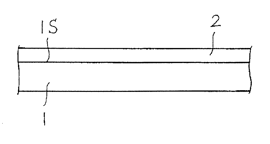
BACKGROUND OF THE INVENTION [0001] 1. Technical Field [0002] The present invention relates generally to nitride semiconductor substrates (wafers), and in particular to nitride semiconductor substrates that are especially utilizable in the manufacture of such components as light-emitting elements, electronic devices, semiconductor sensors, and surface acoustic wave devices. [0003] 2. Description of the Related Art [0004] Components that in recent years are being manufactured using nitride semiconductors include: light-emitting elements such as light-emitting diodes and laser diodes; electronic devices such as rectifiers, bipolar transistors, field-effect transistors, and HEMTs (high electron mobility transistors); semiconductor sensors such as temperature sensors, pressure sensors, radiation sensors, and visible / ultraviolet light detectors; and SAW (surface acoustic wave) devices. [0005] As represented in the schematic cross-sectional view of FIG. 3, such nitride semiconductors are m...

Claims


Application Information

Patent Timeline
Patent Type & Authority Applications(United States)
IPC IPC(8): H01L33/00H01L31/12H01L29/24H01L29/26H01L27/15H01L21/205
CPCC30B29/403H01L21/02389H01L21/02433H01L21/0254H01L29/045H01L29/2003H01L31/184H01L33/16Y10S117/902
Inventor MIYANAGA, MICHIMASAUEMATSU, KOJIOKAHISA, TAKUJI
Owner SUMITOMO ELECTRIC IND LTD
Learn More