Fuel cell system suitable for complex fuels and a method of operation of the same

a fuel cell and complex technology, applied in the field of fuel cell and fuel processing system, can solve the problems of flammability, comparatively high production cost, slow response of steam reforming process, storage difficulties,

Active Publication Date: 2007-05-03
LEONIDA ANDREI
View PDF54 Cites 22 Cited by
  • Summary
  • Abstract
  • Description
  • Claims
  • Application Information

AI Technical Summary

Problems solved by technology

However, hydrogen has a number of drawbacks including: flammability; storage difficulties; and comparatively high production costs.
However, steam reforming is a slow responding process because it relies on thermal energy input to accommodate load changes.
As such, steam reforming is limited mostly to steady state fuel cell operations at temperatures much higher than ambient temperature.
The steady state operating limitation makes such fuel cells impractical for varying power output to follow transient electric load demands.
Moreover, operation of fuel cells at such high temperatures precludes the use of most polymer electrolyte membranes.
However, steam reforming outside a fuel cell increases cost and does not provide improved transient load following capability.
However, storage of highly flammable fuels such as hydrogen is dangerous.
Moreover hydrogen storage facilities generally limit fuel cells to stationary applications.
However, use of methanol is generally not cost-effective enough for widespread application.
Some of these intermediates, however, are known to poison and deactivate the fuel side of catalytic electrodes, essentially stopping the production of hydrogen.
Such polarization redu

Method used


Image

  • Fuel cell system suitable for complex fuels and a method of operation of the same
  • Fuel cell system suitable for complex fuels and a method of operation of the same
  • Fuel cell system suitable for complex fuels and a method of operation of the same

Examples


Embodiment Construction

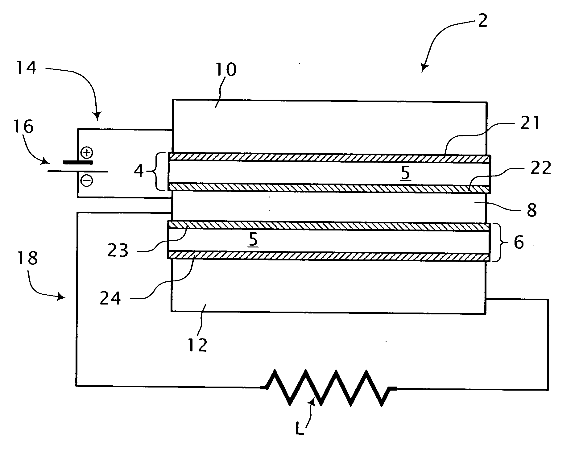
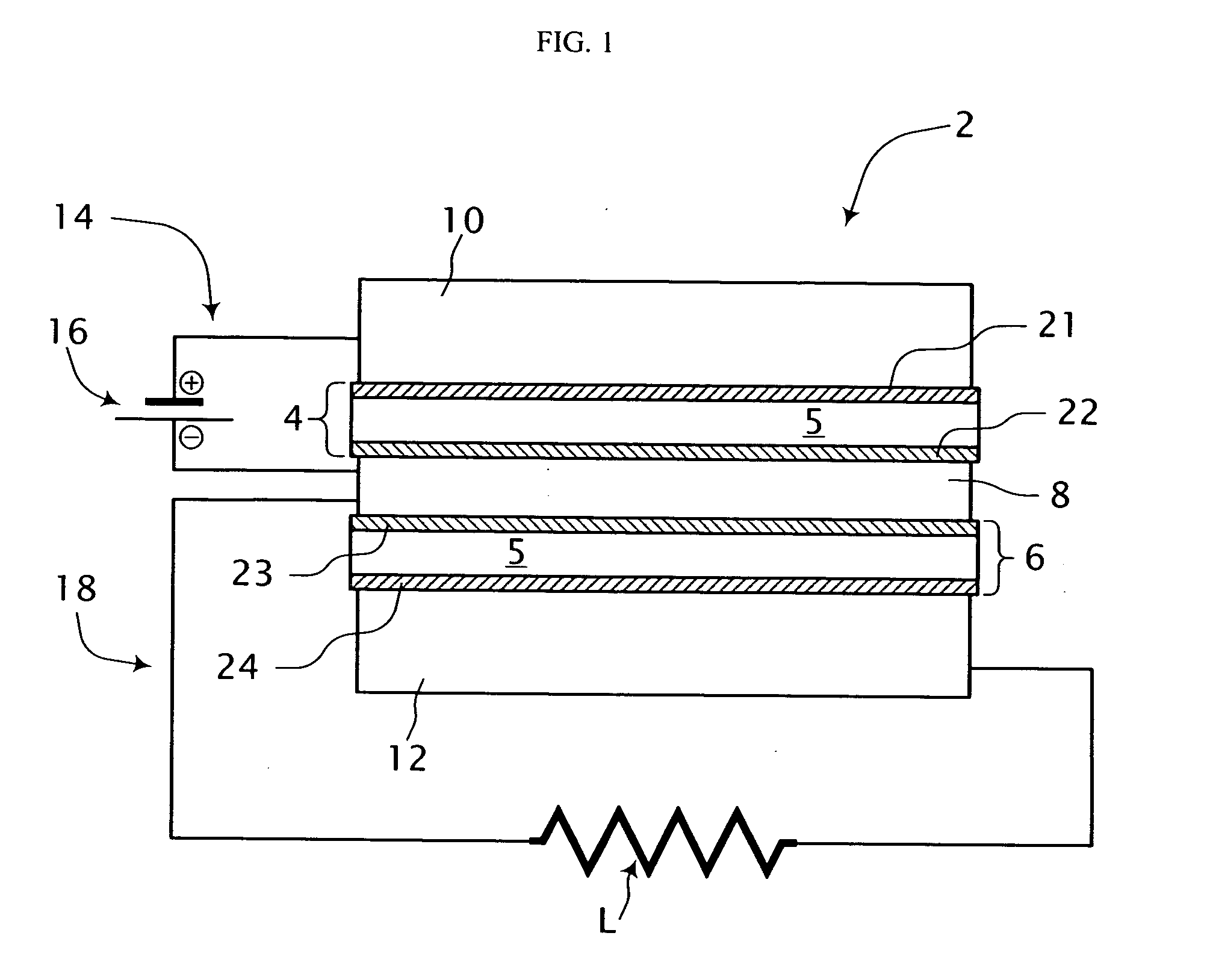
[0035] Referring to FIG. 1, a single cell fuel cell system is shown generally at 2. The fuel cell system 2 includes a first electrode-electrolyte assembly 4, a second electrode-electrolyte assembly 6 and an electrically conductive mesh 8 disposed therebetween and in sealing engagement therewith. A first conduit 10 is in fluid communication with one side of the first electrode-electrolyte assembly 4 and a second fluid conduit 12 is in fluid communication with one side of the second electrode-electrolyte assembly 6. At least portions of the first and second conduits 10, 12 comprise an electrically conductive material. The fuel cell system 2 includes a first electrical circuit 14 including an energy storage device 16 for providing process energy in the form of a first electrical potential across the first electrode-electrolyte assembly 4. In addition, an electrical load circuit 18 is connected across the second electrode-electrolyte assembly 6 for consuming energy output therefrom in t...


PUM


Abstract

A fuel cell system comprising a first electrode-electrolyte assembly having a first electrode coupled to one side of thereof and a second electrode coupled to a generally opposite side of the first electrode-electrolyte assembly, and a first conduit for delivering fuel to the first electrode at ambient temperature. The fuel cell system includes a second electrode-electrolyte assembly having a third electrode coupled thereto assembly, and a fourth electrode coupled to a generally opposite side of the second electrode-electrolyte assembly; and a mesh positioned between and in sealing engagement with the second electrode and the third electrode. A second conduit is in fluid communication with the fourth electrode for delivering oxidant thereto. The fuel cell system further includes means for providing an electrical potential across the first electrode-electrolyte assembly and an electrical load circuit for using an energy output generated across the second electrode-electrolyte assembly.

Description

This application claims priority from provisional application Ser. No. 60 / 731,054, filed Oct. 28, 2005, the disclosure of which is incorporated by reference herein in its entirety.FIELD OF THE INVENTION [0001] The present invention is generally directed to a fuel cell and fuel processing system and a method of operating the same; and is more specifically directed to ambient temperature processing of organic fuels internal to the fuel cell system by electrochemical means. BACKGROUND OF THE INVENTION [0002] Fuel cells are comprised of electrochemical cells used for providing an environmentally clean method for generating electricity. What makes fuel cells different from another electrochemical energy converter, such as a battery, is the fact that both fuel and oxidant are continuously supplied to their respective electrodes, and reaction products are continuously removed from the fuel cell. Electric current will continue to flow essentially as long as fuel and oxidant are supplied to ...

Claims


Application Information

Patent Timeline
IPC IPC(8): H01M8/02H01M8/18H01M4/86H01M8/06
CPCH01M4/8605H01M4/94H01M8/023H01M8/0247H01M8/0258H01M8/0273H01M8/04089H01M8/04223H01M8/04238H01M8/04947H01M8/0625H01M8/0656H01M8/0668H01M8/0681H01M8/1004H01M8/184H01M8/186H01M8/22H01M8/222H01M8/241H01M8/2455H01M16/00H01M16/006H01M2004/8694H01M2008/1095Y02E60/521Y02E60/528Y02E60/50Y02E60/10
Inventor LEONIDA, ANDREI
Owner LEONIDA ANDREI
Why Eureka
Try Eureka