Tubular signal transmission device and method of manufacture

Inactive Publication Date: 2007-05-10
DYNO NOBEL INC
View PDF60 Cites 2 Cited by
  • Summary
  • Abstract
  • Description
  • Claims
  • Application Information

AI Technical Summary

Benefits of technology

[0016] Various optional aspects of the invention which may be embodied individually or in various combinations. Optionally, for example, the interior of the confinement tube may be substantially free of pulverulent reactive material. Optionally, the reactive polymeric material may comprise a GAP material. The signal transmission tube may comprise a l

Problems solved by technology

One art-recognized difficulty is migration of the unembedded pulverulent reactive material, which is conventionally held in place only by electrostatic or other attraction to the plastic of which the interior surface of the tube is made.
During shipment, handling or installation, portions of the pulverulent reactive material tend to detach from the tube wall, possibly resulting in bare spots on the interior of the tube and/or accumulation of powder, especially in kinks or in curved portions of the tube, which then may be plugged with the loose reactive powder that may interrupt the transmission of a signal therethrough, resulting in a misfire.
Powder migration is a problem because, in products where lengths of the signal transmission fuse are connected to devices such as detonators, migrating powder can collect atop the explosive or pyrotechnic contained within the detonator and shield the explosive or pyrotechnic from the signal generated in the shock tube, thereby resulting in a misfire.
Localized concentrations of powder can lead to blow-outs of the tube wall which will result in undesired variations of the reaction pressure.
Of course,

Method used


Image

  • Tubular signal transmission device and method of manufacture
  • Tubular signal transmission device and method of manufacture

Examples


Embodiment Construction

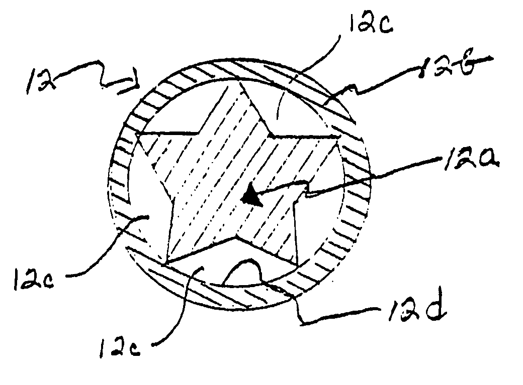
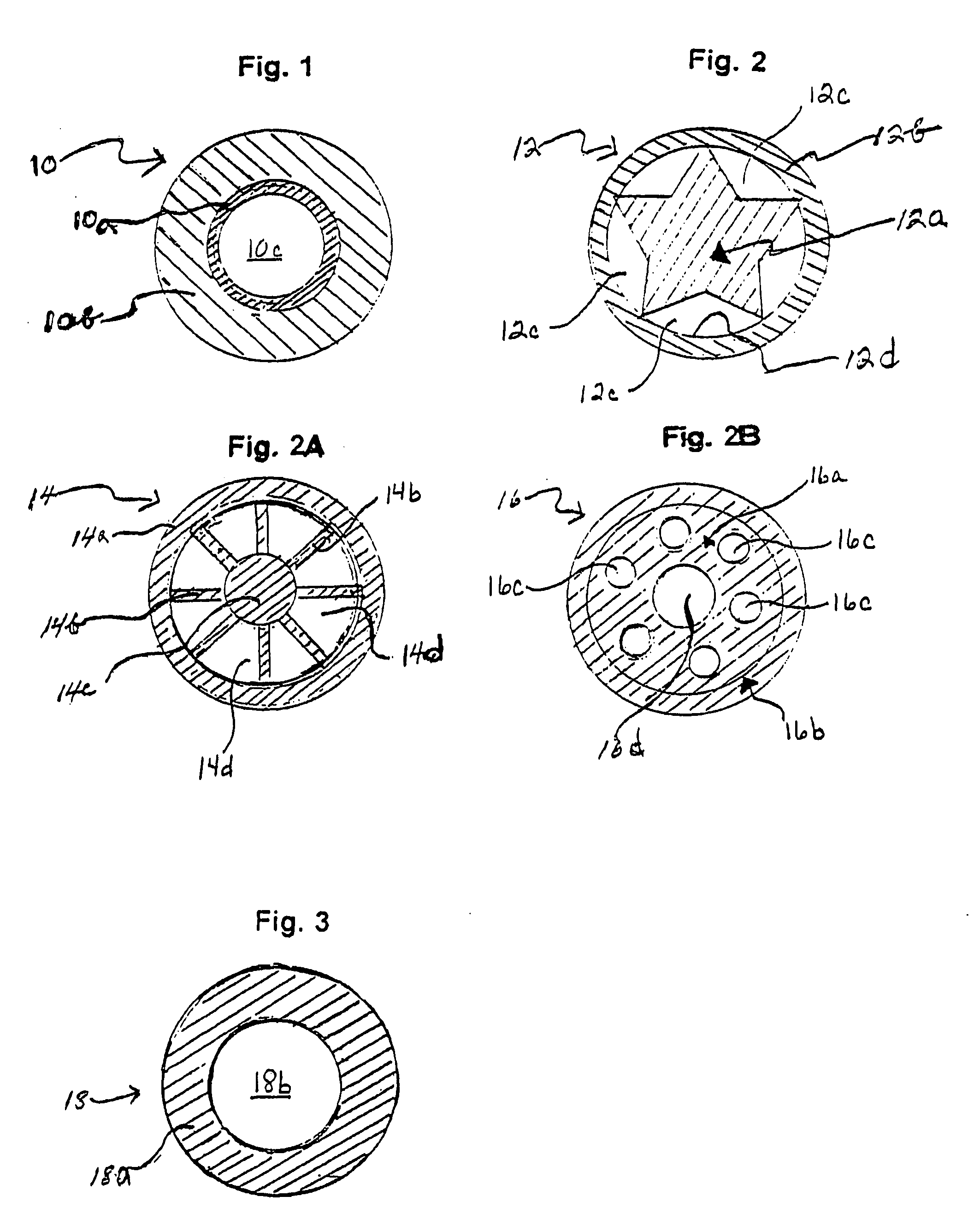
[0024] A signal transmission tube as described herein comprises, instead of pulverulent reactive material, a reactive polymeric material. In some embodiments, the signal transmission tube comprises a confinement tube within which the reactive polymeric material is disposed as a rod within the confinement tube or as a layer of a coating composition (e.g., a paint) on the interior surface of the tube. In such embodiments, the confinement tube is preferably made of a non-reactive material or materials, such as the single- or multiple-ply hollow polyethylene and / or SURLYN® tubes conventionally used in shock tubes.

[0025] Reactive polymeric materials are polymeric materials that have reactive pendant groups such as azido groups, nitrate groups, triazoline groups and / or triazole groups chemically bonded to the polymer backbone, rather than comprising a relatively inert polymeric material or resin having pulverulent reactive material physically blended therein. However, a reactive polymeri...


PUM


Abstract

A signal transmission tube may be made by disposing a reactive polymeric material within a confinement tube and leaving a portion of the tube interior unoccupied. The tube may be formed by disposing a layer of paint comprising the reactive polymeric material on the interior surface of the confinement tube, extruding the confinement tube over an elongate rod that comprises the reactive polymeric material. The rod preferably has a high surface area configuration, e.g., the rod may comprise a longitudinal bore therethrough or may be star-shaped, cross-shaped, etc. Alternatively, the signal transmission tube may be made from the reactive polymeric material. Optionally, a sheath may be extruded over the tubular reactive polymeric material. In various embodiments, the confinement tube or sheath may be configured to be fractured or substantially consumed by the reaction of the reactive polymeric material. Optionally, the reactive polymeric material may comprise a glycidyl azide polymer.

Description

BACKGROUND OF THE INVENTION [0001] 1. Field of the Invention [0002] This invention relates to initiation signal transmission lines used in mining and other blasting operations and, in particular, to tubular initiation signal transmission lines such as shock tube and low velocity signal tube. [0003] 2. Related Art [0004] U.S. Pat. No. 5,681,904 entitled “Azido Polymers Having Improved Burn Rate”, issued Oct. 28, 1997 and relates to azido polymers, especially cross-linked azido polymers that can be used as high-energy materials. As disclosed starting at column 1, line 10, azido-containing compounds and polymers are important in the fields of explosives and propellants because the azido group is highly energetic and can easily be incorporated into a polymer or oligomer at high weight percent loadings. One especially useful class is described starting at column 1, line 14, as azido-substituted polyethers, for example, glycidyl azide polymer. Although hydroxylated azido-substituted polye...

Claims


Application Information

Patent Timeline
IPC IPC(8): F42B3/10F42B4/00C06C5/04
CPCC06C5/04F42D1/04
Inventor BAYLISS, JAMESGLADDEN, ERNEST L.TWAROG JR., JOSEPH W.
Owner DYNO NOBEL INC
Why Eureka
Try Eureka