
Non-isolated DC-DC converters with direct primary to load current

a dc-dc converter and primary load technology, applied in the field of dc-dc converters, can solve the problems of significant overshoot of voltage across the cpu, damage to the cpu, and the inability of 12v dc voltage to power the cpu directly, so as to reduce the size of the output capacitor and reduce the ripple incoming to the output capacitor

Inactive Publication Date: 2007-05-10
GANPOWER INT INC
View PDF8 Cites 24 Cited by
  • Summary
  • Abstract
  • Description
  • Claims
  • Application Information

AI Technical Summary

Benefits of technology

[0021] Alternatively, the auxiliary section may have a first switch connected between a first side of the first primary winding and the first voltage input, a first capacitor connected between a second side of the first primary winding and the first voltage input, a second switch connected between the first side of the first primary winding and the high side circuit output, and a second capacitor connected between the second side of the first primary winding and the high side circuit output. Each switch may have an input for a gate drive signal for controlling the operation of the switch. The converter may include gate drive signals adapted to repeatedly turn on and turn off the first switch and second switch, whereby the first transformer can be reset from the capacitors. The capacitors may be large enough that the voltage across the capacitors will not change significantly during normal operation of the converter.
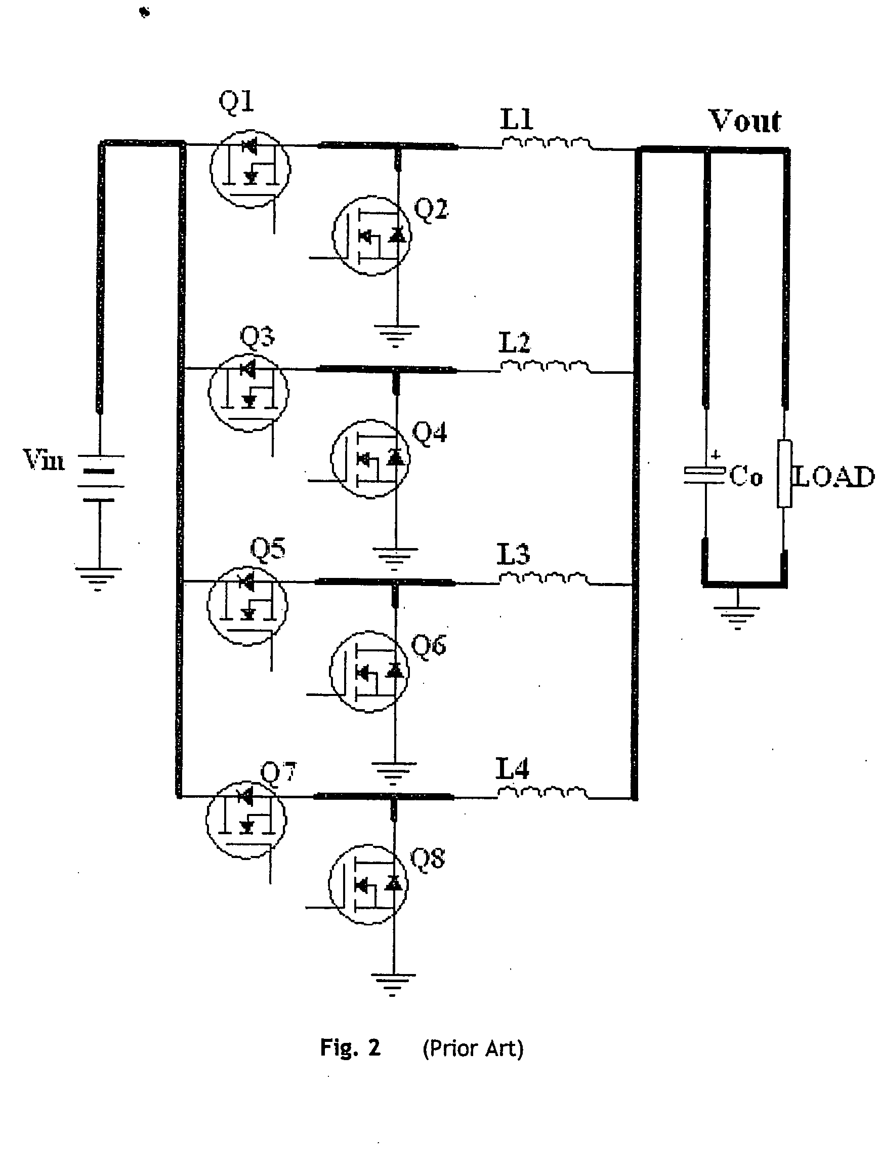
[0030] The converter may have a second converter similar to the first converter, wherein the two converters are connected in parallel with one another at their respective inputs and outputs. The output capacitors of the two converters may be combined as a single physical capacitor. The two converters may have interleaved gate drive signals, whereby current ripple incoming to the output capacitor is reduced, allowing for reduction in the size of the output capacitor.

Problems solved by technology

This 12V DC voltage cannot power the CPU directly.
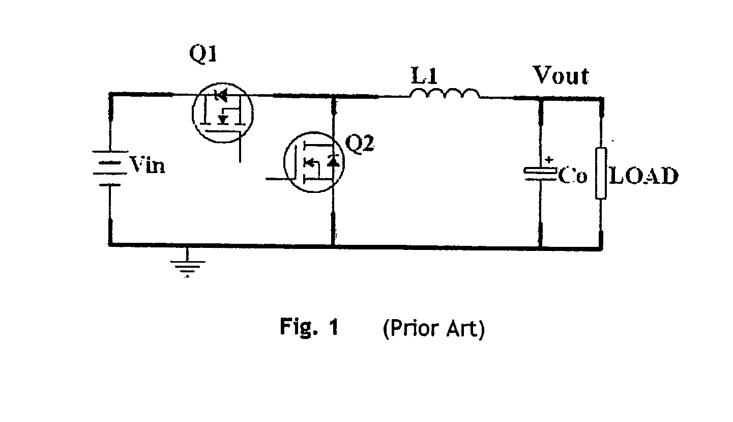
If the response speed of the converter is not fast enough, the voltage across the CPU will have significant overshoot during the transition from large CPU current to low CPU current because an inductor is typically used in the converter.
This voltage overshoot could cause damage to the CPU.
Similarly, the voltage across the CPU will have significant undershoot during the transition from low CPU current to large CPU current.
If the voltage is too low, the CPU may not operate properly.
It is noted that a small duty cycle such as 7% is not optimal for the design and operation of a Buck converter when the switching time of the MOSFET (“metal-oxide semiconductor field-effect transistor”) is considered.
Considering the delay time of the controller, it is very difficult to design an actual implementation.
In addition, operating at a very small duty cycle has another detrimental impact to the dynamic response.
Nevertheless, the duty cycle can only be reduced from 7% to 0%.
The duty cycle has only 7% change, which results in poor dynamic response.
However, each Buck converter still operates at very small duty cycle, which is not desirable.

Method used


Image

  • Non-isolated DC-DC converters with direct primary to load current
  • Non-isolated DC-DC converters with direct primary to load current
  • Non-isolated DC-DC converters with direct primary to load current

Examples


Embodiment Construction

[0152] Referring to FIG. 3, a non-isolated DC converter 301 (outlined in dashed lines) consists of three blocks: high side circuit 305, rectifier circuit 307 and output filter capacitor Co. The high side circuit 305 connects directly between positive point Vin+ of the input voltage Vin and the positive point Vout+ of the output Vout. The high side circuit 305 is therefore not isolated from the rectifier circuit 307 and, thus, the converter is “non-isolated”.

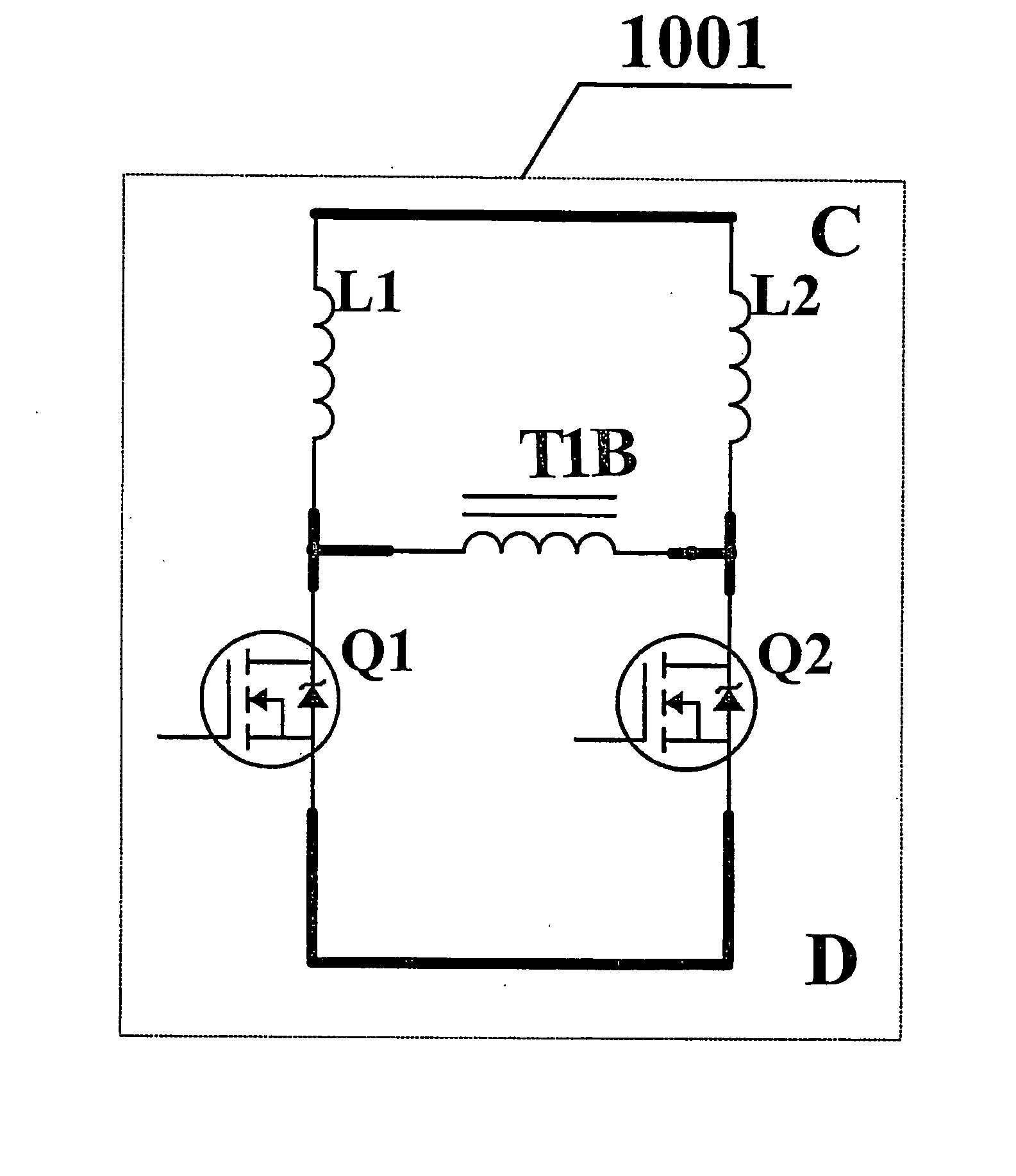
[0153] As will be discussed, the high side circuit 305 includes one or more transformer primary winding(s) and an auxiliary section that will operate the transformer(s) properly. This auxiliary section may consist of switches (such as MOSFET, BJT (“bipolar junction transistor”), etc). This auxiliary section may also consist of a combination of switches and capacitors. The function of this auxiliary section is to make the transformer operate properly. The term “operate properly” means that the transformer will not saturate and th...


PUM


Abstract

DC-DC converters have high side and rectifier circuits, and output capacitor. High side circuit connects between input voltage and output voltage, and has primary winding and auxiliary section that operate transformer properly. Auxiliary may have switches or combination of switches and capacitors. High side circuit converts electrical into magnetic energy through transformer primary, which is then transferred to output through rectifier circuit. It also transfers energy directly to output voltage. Converters have high efficiency, fast dynamic response and high current output. Converters can have large duty cycle and large input voltage and output voltage conversion ratio. High side circuit can be half-bridge, full-bridge or forward converter. Rectifier uses inductors on either side of the secondary, and diodes or synchronous rectifiers, to rectify output voltage. Multi-phase interleaved circuits utilize shared switches to reduce size. High side circuit can utilize resonant tank to decrease switching losses in auxiliary.

Description

CROSS REFERENCE TO RELATED APPLICATIONS [0001] This application claims priority from and is entitled to the benefit of the filing date of U.S. Provisional Patent Application No. 60 / 431,740 filed 9 Dec. 2002 under the same title and by the same inventors.FIELD OF THE INVENTION [0002] The invention relates to DC-DC converters. More particularly, it relates to such converters for low voltage central processing unit applications. BACKGROUND OF THE INVENTION [0003] Computers are widely used both in our personal life and in our work. The heart of the computer is the central processing unit (CPU), which performs all the numerical calculation needed for today's ever demanding operation. In order to increase the calculation speed of the CPU, and, thus the speed of the computer, the voltage required to power the CPU is becoming lower and lower. At the same time, the current that the CPU draws is becoming higher and higher. For example, the next generation CPU will require supply voltage of le...

Claims


Application Information

Patent Timeline
Patent Type & Authority Applications(United States)
IPC IPC(8): H02M3/335H02M3/158H02M3/28
CPCH02M3/158H02M3/1584H02M3/1588H02M3/28H02M3/285Y02B70/1425Y02B70/1466Y02B70/10
Inventor LIU, YAN-FEIYE, SHENG
Owner GANPOWER INT INC
Learn More