Interactive transparent individual cells biochip processor

a biochip processor and transparent technology, applied in the field of new interactive transparent individual cells biochip processors, can solve the problems of complex compound study based on isolated targets or cell preparations, limited assays, and cell-based assay procedures

Inactive Publication Date: 2007-05-10
BAR ILAN UNIV
View PDF98 Cites 54 Cited by
  • Summary
  • Abstract
  • Description
  • Claims
  • Application Information

AI Technical Summary

Benefits of technology

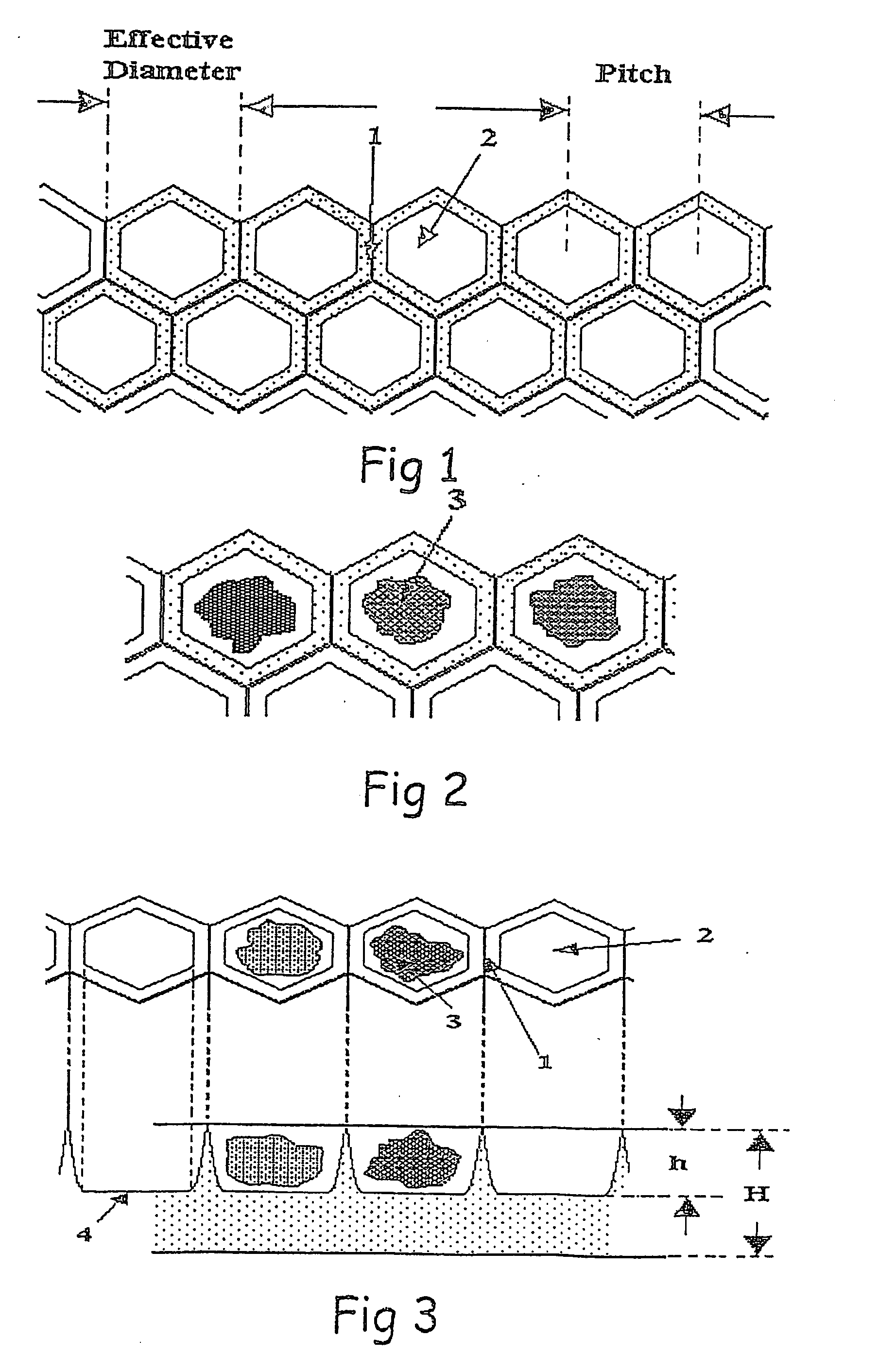
[0047] 1. High quality transparency that makes the individual cell visible while being held and maintained via the well and consequently, morphologically examinable.
[0051] 4. The ITICBP device can accommodate, simultaneously and in a non-disturbing way, large cell populations, on a cell-by-cell basis. For example, it may easily comprise 9 fields of 150×150 micron-sized-wells each with separating channels in between, thus permitting simultaneous exposure of the 9 fields (each field populated with 22,500 individual cells of same or different source and / or type) to at least 9 different biological and / or biochemical and / or flourophoric—active agents.
[0058] The ITICBP is mounted on a computer-controlled stage and positioned to place the investigated cell at the point of interrogation (at the center of an excitation laser beam or field of measurement / observation / manipulation). The address of each cell, determined by its location on the ITICBP, is maintained throughout a series of measurements and manipulations to which the cell is subjected. Holding the cells on the ITICBP, allows them to be maintained under the favorable conditions while various stimuli are added or rinsed away.

Problems solved by technology

Many times, a compound study based on isolated targets or cell preparations can not resolve this complexity.
Still, these assays are limited in the minimal sample size they may measure and none of them allows individual cell-based assay procedure.
Therefore, it is impossible to perform a series of sequential static and dynamic measurements on the same individual cell.
Many who have developed and used the apparatus and techniques of flow cytometry have come to the realization that some of the most critical questions in various areas of cell and developmental biology, immunology, oncology, and pharmacology cannot be answered using even the most sophisticated flow cytometers.
Consequently, once a subgroup has been identified only its cells are investigated, thereby limiting investigation time only to the subgroup cells which are of interest.
This is a huge deficiency in many fields of research and application since there is no way to correlate between the measured data (i.e. fluorescence intensity (FI), fluorescence polarization or anisotropy (FP), fluorescence lifetime (FLT), fluorescence polarization decay (FPD) and electrode-based reactions) and visually observed data_(i.e. morphology, shape, intracellular compartments etc.).
As a consequence, when by chance more than one single cell is trapped in the same hole-trap, the measured data obtained from that trap cannot be distinguished and associated with any of the trapped cells specifically.
(e) Due to strong reflections, even when a blackened CC is used, scattered light measurements of a single trapped cell in the CC are unrealisable.
(f) One undesired outcome of the electroplating technique is the flat spaces (or very moderately curved) created among holes as can be seen in FIGS. 19-22 of U.S. Pat. No. 5,506,141.
Hence, a high proportion of the loaded cells settle down between holes rather than inside them, a fact which decreases loading efficiency, causes waste of cells, which might be curtail when the sample size is limited.
(g) Trapped cell toxicity induced by the metallic CC is inevitable due to the release of metallic ions in physiological environment.
(h) The level of smoothness of a hole-trap wall, as well as of the intermediate spaces, is quite limited (see FIGS. 20-22, 36 and 32 in U.S. Pat. No. 5,506,141) due to intrinsic limitations of manufacturing processes.
(i) Electromagnetic manipulation at the proximity (vicinity) of the CC metallic surface is quite limited and insufficient due to mirror effects.
(j) Fabrication of microelectrodes in the metallic traps, is impossible.
The operation efficiency of these kinds of uses strongly suffers from electrical screening effects caused by the free ions of the buffering physiological suspending media.
Moreover, an additional undesired effect is electrolysis, which alters the suspending media characteristics and might cause cell death as mentioned in U.S. Pat. No. 5,506,141 (column 14, lines 64-65): “The use of an electric field as the driving force can lead to electrolysis problems”.

Method used


Image

  • Interactive transparent individual cells biochip processor
  • Interactive transparent individual cells biochip processor
  • Interactive transparent individual cells biochip processor

Examples


example

Measuring Intracellular Nonspecific Esterase Activity in a Single Lymphocyte Using Fluorescein-Diacetate (FDA) as the Substrate

[0345] (a) Materials and Methods:

[0346] Phytohemagglutinin PHA) HA15, Murex Biotech) was reconstituted in 5 ml of double-distilled water and further diluted ten times. For stimulation, 10 μl of this solution was added to a 90 μl cell suspension (7×10⁶ cells / ml).

[0347] The culture medium consisted of RPMI-1640 (Biological Industries), supplemented with 10% (v / v) heat-inactivated fetal calf serum (Biological Industries), 2 mM L-glutamine, 10 mM Hepes buffer solution, 1 mM sodium pyruvate, 50 U / ml penicillin and 50 Units / ml streptomycin.

[0348] A staining solution of 3.6 μM FDA (Riedel-de Haen Ag. Seelze-Hanover) in Dulbecco Phosphate Buffered Saline (PBS, Biological Industries) was prepared as follows: 50 mg of FDA was dissolved in 5 ml of DMSO (Sigma). 7.5 μl of this solution was added to 50 ml PBS. For 0.6, 1.2 and 2.4 μM the solution was further diluted ...


PUM

PropertyMeasurementUnit
depthaaaaaaaaaa
diameteraaaaaaaaaa
diameteraaaaaaaaaa

Abstract

An Interactive Transparent Individual Cells Biochip Processor (ITICBP) device is described, which is useful for assessing a single, individual living cell at identifiable location or assessing group of cells each at identifiable location.

Description

RELATED APPLICATIONS [0001] This application is a U.S. Divisional Application of U.S. application Ser. No. 10 / 492,531, filed on Apr. 26, 2004, which is a U.S. National Phase of PCT Application No. PCT / IL01 / 00992, filed on Oct. 25, 2001. The contents of the above Applications are all incorporated herein by reference.FIELD OF THE INVENTION [0002] The present invention relates to a new Interactive Transparent Individual Cells Biochip Processor (ITICBP) device which suggests a new generation of cytometer, referred to as Lab on a Cell Chip device, applicable in determination of activity of an identified same, or different, single cell. More specifically, the new ITICBP device allows on-line measurement of a vast spectrum of physiological activities of an visually observable individual cell, or a group of cells, using a wide-range of methods such as, morphometry, fluorescence, chromometry, reflectance, electrochemical, and other chemical- and optical-based procedures. These new capabiliti...

Claims


Application Information

Patent Timeline
Patent Type & Authority Applications(United States)
IPC IPC(8): C12Q1/00G06F19/00C12M1/34G01N33/48B01L3/00C12M3/00C40B60/14G01N15/10G01N15/14G01N27/30G01N27/416G01N35/00G01N35/04G02B21/34
CPCB01J2219/00317B01J2219/00702B01L3/5027B01L2300/0681B01L2300/0877C12M23/12C12M25/08C12M41/46C40B60/14G01N15/1475G01N15/1484G01N33/5005G01N2015/1006G01N2015/1472G01N2015/1497G01N2035/00158G01N2035/0429G02B21/34
Inventor DEUTSCH, MORDECHAI
Owner BAR ILAN UNIV
Why Eureka
Try Eureka