Printed-circuit board having a plastic part for accommodating a measuring device

a technology of measuring device and printed circuit board, which is applied in the direction of measurement device, volume/mass flow measurement, instruments, etc., can solve the problems of sensor gel running out, sensor chip air flow changing, and characteristic curve drifting, etc., to achieve cost-effectiveness, improve quality, and improve production efficiency

Active Publication Date: 2007-05-17
ROBERT BOSCH GMBH
View PDF7 Cites 23 Cited by
  • Summary
  • Abstract
  • Description
  • Claims
  • Application Information

AI Technical Summary

Benefits of technology

[0011] On the other hand, the printed circuit board may be produced directly having a sheet metal plate in one process (heat sink technology). An SBU heat sink printed circuit board may be used as a substitute for a thick film. A printed circuit board manufactured according to heat sink technology, i.e. an SBU (sequential built up) printed circuit board, represents a printed circuit board developed in multilayer fashion. This may be used as a circuit substrate using a ceramic substrate. The SBU heat sink printed circuit board may be developed as a printed circuit board, patterned on both sides, having microvias and a chemically galvanized copper layer. Such SBU heat sink printed circuit boards are later clamped to the accommodation made of plastic for the sensor chip, or adhered, welded or fitted in a different manner. The last-named alternative stands out because of favorable production costs, since the printed circuit board patterning is produced directly connected to a me...

Problems solved by technology

Corrosion products that form on the air flow sheet metal lead to a changed air flow to the sensor chip, and thus to a drift in its characteristics curve.
An additional cause of the characteristics curve drift is the running out of the senso...

Method used


Image

  • Printed-circuit board having a plastic part for accommodating a measuring device
  • Printed-circuit board having a plastic part for accommodating a measuring device
  • Printed-circuit board having a plastic part for accommodating a measuring device

Examples


Embodiment Construction

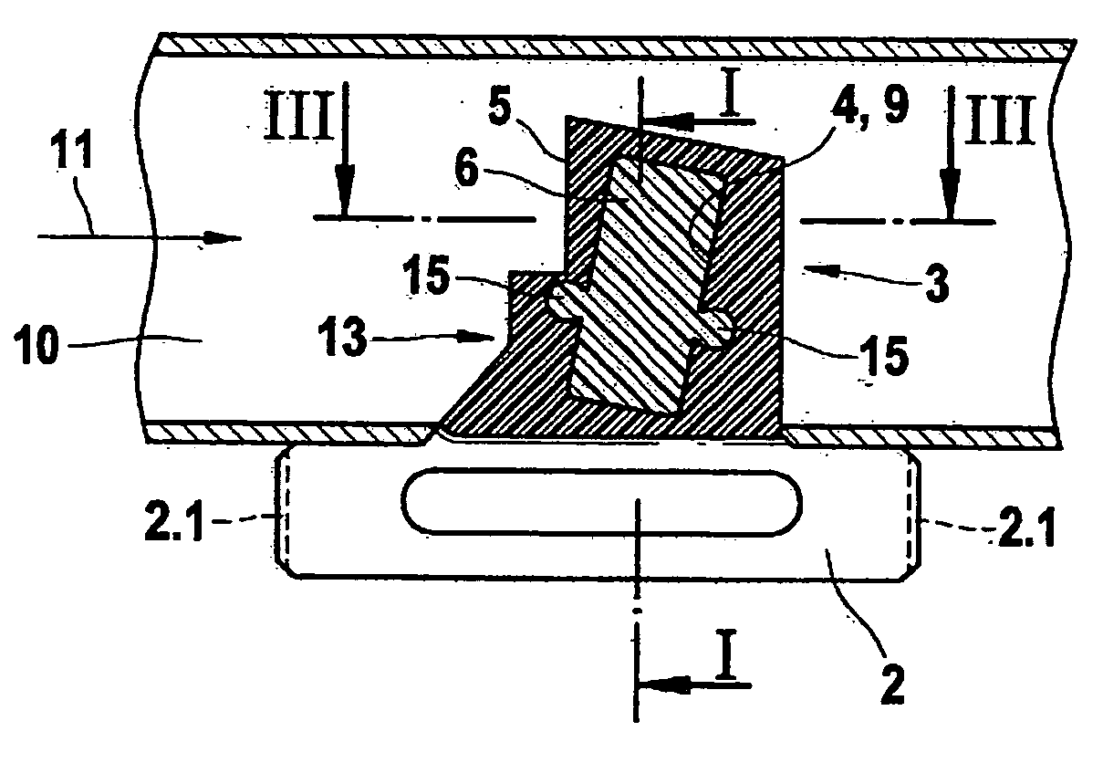
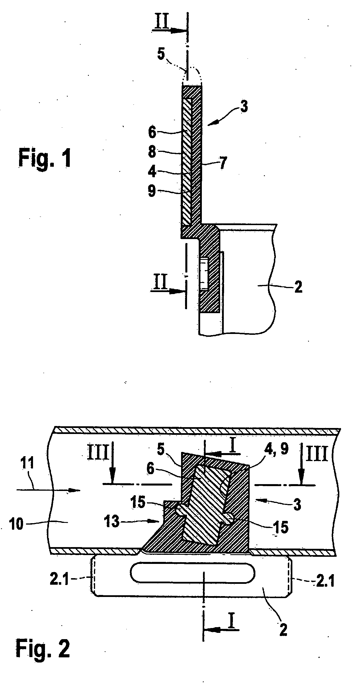
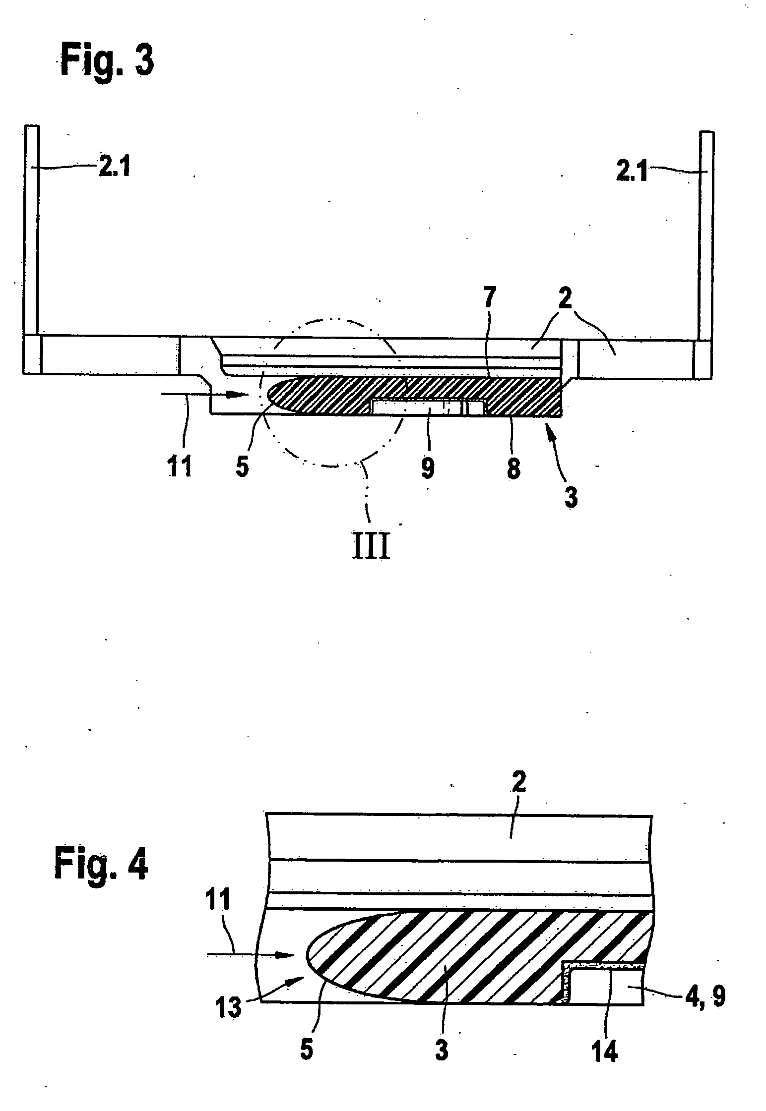
[0021] In FIG. 1 one may see, on a considerably enlarged scale, a plastic tongue for accommodating a sensor chip. Onto an electronic module 2, there is laterally extruded on a plastic substrate tongue 3. The plastic substrate tongue includes a recess 4 having a flat floor area, into which a sensor chip 6 may be inserted. Plastic substrate tongue 3, according to the illustration in FIG. 1, extends into a bypass channel, not shown in FIG. 1, which has a flowing medium flowing through it. The flowing medium sweeps over plastic substrate tongue 3 both on side 8, at which sensor chip 6 is accommodated and on back side 7. Recess 4, inside plastic substrate tongue 3, is constituted as cavity 9, and encloses sensor chip 6 on all sides. At plastic substrate tongue 3 an air flow edge 5 is formed which, according to the illustration in FIG. 1, may be formed as a round shape. Sensor chip 6, that is insertable into recess 4 that is constituted as a cavity 9, is preferably developed in a height t...


PUM


Abstract

The arrangement relates to a hot-film mass flow meter for recording the flow rate of a flowing medium in the intake tract or the charge air tract of an internal combustion engine. A substrate part is provided, that accommodates a sensor chip, which is allocated to a channel that has flowing through it at least one partial mass flow of the flowing medium. The sensor chip extends into channel that has flowing through it the partial mass flow of the flowing medium. The substrate part is formed either as a separately extruded plastic tongue or as a cavity extruded of plastic material. The sensor chip is integrated downstream with respect to a flow direction of the flowing medium, so as to lie behind a leading edge.

Description

FIELD OF THE INVENTION [0001] Flow rate meters are used to determine the rate of air flow in the intake tract or the charge tract of an internal combustion engine. Since the chemical process of combustion depends on the mass ratios, the mass flow rate of the intake / charge air has to be measured, for which, in part, volume-measuring or ram pressure measuring methods are also used. However, the maximum air mass flow that is to be measured, depending on the engine performance, is in the range between 400 to 1000 kg / h. BACKGROUND INFORMATION [0002] From Automotive Handbook 23rd, updated and expanded edition, Braunschweig, Wiesbaden, Viehweg, 1999, ISBN 3-528-03876-4, pp. 116 and 117, micromechanical hot-film air mass meters of the smallest dimensions are known, that work according to thermal principles. In these, heating and measuring resistors are sputtered, i.e. vapor-deposited, as thin Pt layers onto a silicon chip as carrier. The silicon chip is accommodated in the region of the hea...

Claims


Application Information

Patent Timeline
IPC IPC(8): G01F1/68G01F1/684G01F1/692
CPCG01F1/684G01F1/6842G01F5/00
Inventor STROHRMANN, MANFREDSCHARD, RAINER
Owner ROBERT BOSCH GMBH
Why Eureka
Try Eureka