
Endoluminal implant with therapeutic and diagnostic capability

a technology of endoluminal implants and diagnostic capabilities, which is applied in the field of endoluminal implants with, implantable medical devices, can solve the problems of inability to supply power to such sensors, use of conventional sensors, and inability to solve problems such as practical solutions, so as to facilitate localized drug delivery, prevent further tissue growth, and improve the effect of medical treatment of patients

Inactive Publication Date: 2007-05-17
CARDIOMETRIX
View PDF4 Cites 68 Cited by
  • Summary
  • Abstract
  • Description
  • Claims
  • Application Information

AI Technical Summary

Benefits of technology

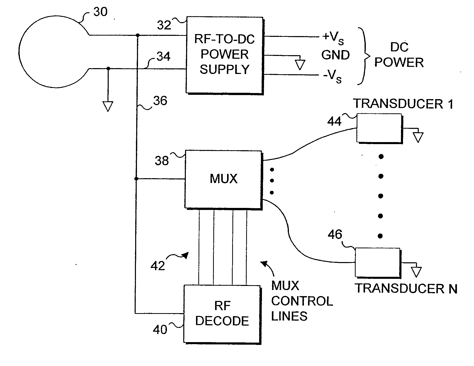
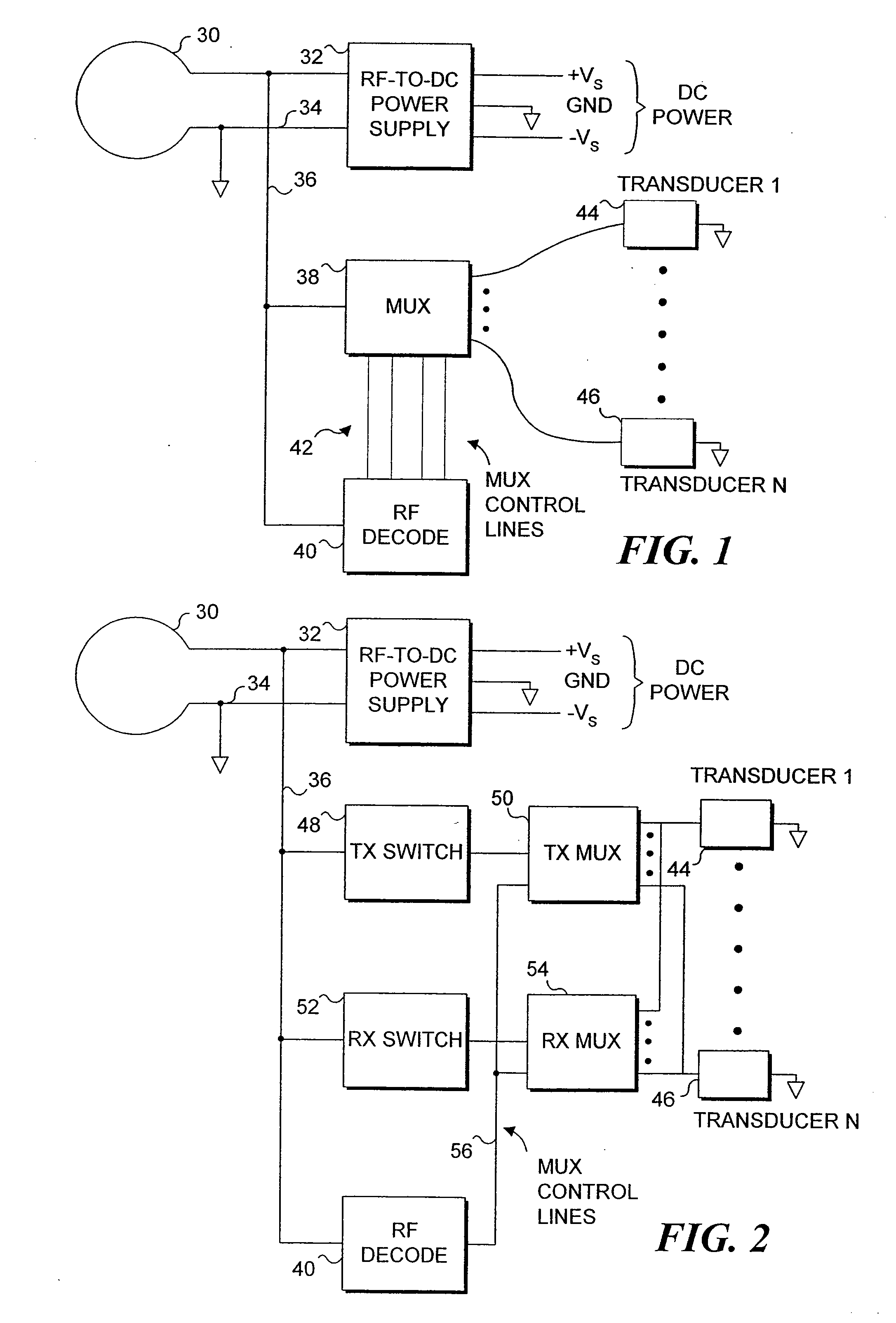
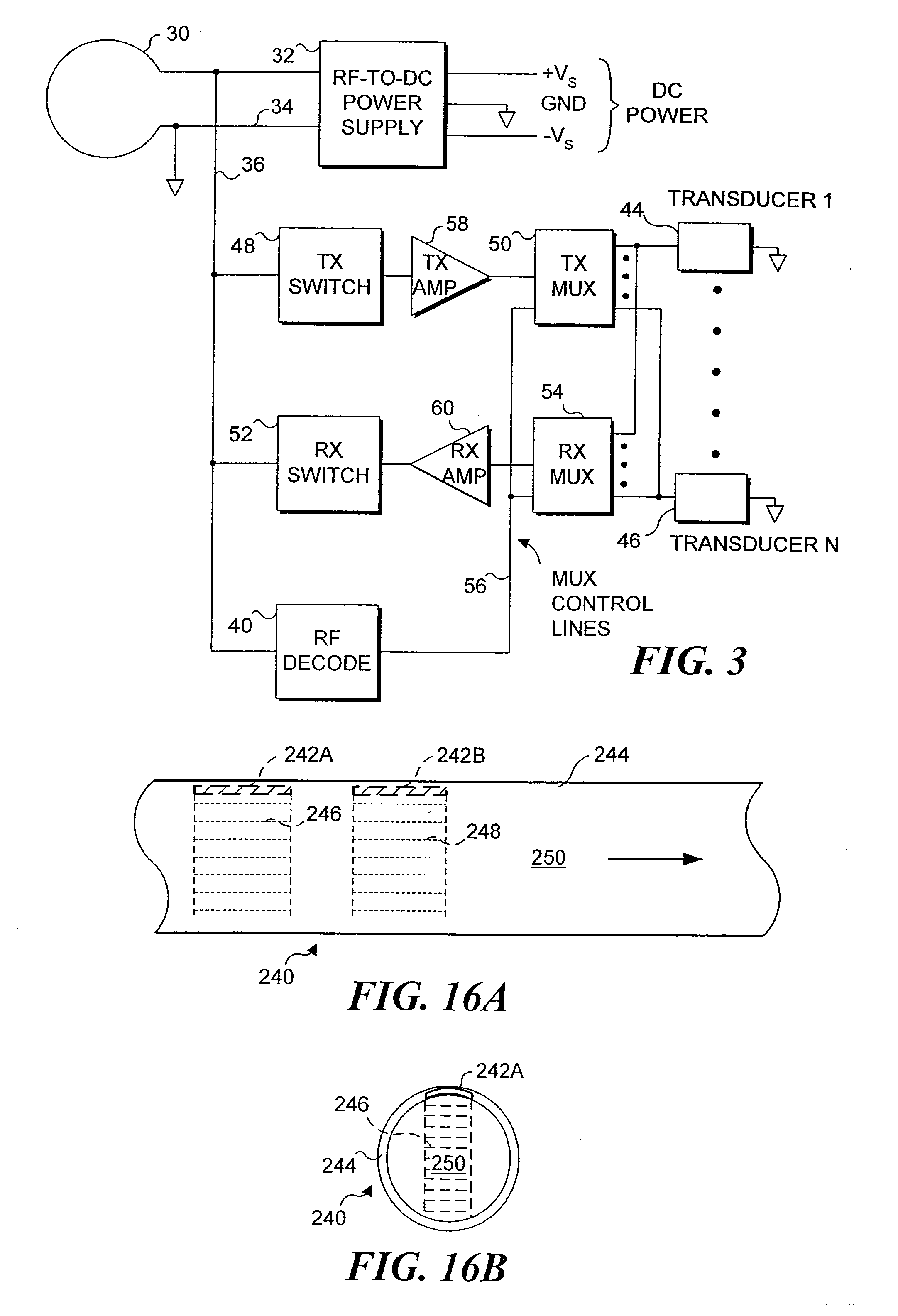
[0007] The present invention provides a capability for including a therapeutic transducer together with an endoluminal implant such as a stent or stent graft. Therapeutic transducers may include ultrasonic, magnetic, iontophoretic, heating or optical devices, which may permit localized drug delivery or localized drug activation. Provision is made for delivering energy to the implanted transducers and for coupling signals to or from the implanted transducers. The present invention also permits inclusion of diagnostic transducers together with the endoluminal implant and allows signals to be transmitted from the diagnostic transducers to an area outside of the patient's body.
[0008] The present invention can allow steps that may be taken to restore full fluid flow through, e.g., a stent that is becoming restricted. In these cases, it is desirable to initiate treatment before the problem proceeds too far to be corrected without stent replacement or further PTCA treatment. Clearly, it would be preferable to be able to monitor the condition of a stent without resorting to invasive surgical procedures and without prescribing medication that may not be necessary, so that the useful life of the stent may be extended, problems associated stent failure avoided and so that medications are only prescribed when required by the known condition of the stent and associated vasculature.
[0012] Endoluminal implants are used in other body passages in addition to blood vessels. For example, they are sometimes used to maintain an open lumen through the urethra, or through the cervix. A stent placed adjacent to an enlarged prostate gland can prevent the prostate from blocking the flow of urine through the urethra. Tracheal and esophageal implants are further examples of endoluminal implants. In these and other uses of endoluminal implants, provision for monitoring parameters related to the status of flow and other conditions in the patient's body is desirable. Information provided by monitoring such parameters, and localized drug delivery or drug activation, can enable more effective medical treatment of a patient through use of embodiments of the present invention.
[0013] Another advantage that may be realized through practice of embodiments of the present invention is to be able to activate a therapeutic device on the stent or stent graft that would allow the physician to activate drugs known to be effective in preventing further tissue growth within the stent or stent graft in situations where it is determined that tissue ingrowth is threatening the viability of a stent or stent graft. Again, the therapeutic device should be able to be supplied with electrical power from time to time from a location outside the patient's body.
[0014] Yet another advantage that may be realized through practice of the present invention is the treatment of tumors or organs that are downstream of the blood vessel that includes a stent that is coupled to a transducer. The transducer may be remotely activated to facilitate localized drug delivery or to provide other therapeutic benefits.

Problems solved by technology

Since it is impractical to pass a conductor through the wall of an artery or vessel for long periods of time, use of a conventional sensor that produces signals indicative of flow through a stent, which must be conveyed through a conductor that extends through the wall of the vessel and outside the patient's body, is not a practical solution to this problem.
Again, it is not practical to supply power to such a sensor through any conductor that perforates the vessel wall or that passes outside the patient's body.

Method used


Image

  • Endoluminal implant with therapeutic and diagnostic capability
  • Endoluminal implant with therapeutic and diagnostic capability
  • Endoluminal implant with therapeutic and diagnostic capability

Examples


Embodiment Construction

[0050] The present invention is employed for providing therapeutic functions proximate to an endoluminal implant. As used herein and in the claims that follow, the term endoluminal implant broadly encompasses stents, stent grafts (sometimes referred to as “spring grafts”) and other types of devices that are inserted into a lumen or body passage and moved to a desired site to provide a structural benefit to the lumen. To simplify the disclosure of the present invention, most of the following discussion is directed to embodiments comprising a stent.

[0051] In one embodiment, parameters are monitored via implanted diagnostic transducers, where the monitored parameters are directed to determining the status of the fluid flow through the endoluminal implant, and therapeutic transducers may be activated in response to the data collected from the implanted diagnostic transducers. For example, the rate or velocity of fluid flow through a body passage in which the stent has been positioned c...


PUM


Abstract

An apparatus includes an endoluminal implant, a RF coupling coil coupled to the endoluminal implant and a therapeutic transducer electrically coupled to the RF coupling coil and physically coupled to the endoluminal implant. The RF coupling coil supplies electrical power to the therapeutic transducer. The therapeutic transducer has a capability for delivering therapeutic energy to a lumen disposed within the endoluminal implant in response to signals coupled via the RF coupling coil.

Description

TECHNICAL FIELD [0001] This invention relates generally to implantable devices, and, more particularly, to implantable medical devices having therapeutic or diagnostic functions within a lumen of an endoluminal implant such as a stent or other type of endovascular conduit, and methods related to such implantable medical devices. BACKGROUND OF THE INVENTION [0002] In the 1970s, the technique of percutaneous transluminal coronary angioplasty (PTCA) was developed for the treatment of atherosclerosis. Atherosclerosis is the build-up of fatty deposits or plaque on the inner walls of a patient's arteries; these lesions decrease the effective size of the artery lumen and limit blood flow through the artery, prospectively causing a myocardial infarction or heart attack if the lesions occur in coronary arteries that supply oxygenated blood to the heart muscles. In the angioplasty procedure, a guide wire is inserted into the femoral artery and is passed through the aorta into the diseased cor...

Claims


Application Information

Patent Timeline
Patent Type & Authority Applications(United States)
IPC IPC(8): A61B18/18A61B5/00A61B8/04A61B8/06A61F2/02A61F2/07A61F2/82A61M1/36A61M37/00A61N1/30A61N1/32A61N5/06
CPCA61B5/0031A61B5/14532A61B5/6862A61B5/6876A61B8/04A61B8/06A61B8/12A61B8/56A61B2560/0219A61F2/07A61F2/82A61F2002/072A61F2002/075A61F2250/0001A61F2250/0002A61M37/0092A61N1/306A61N1/325A61N5/0601A61N5/062A61M1/3656A61B8/4483
Inventor KEILMAN, GEORGE W.
Owner CARDIOMETRIX
Learn More