Wing load alleviation apparatus and method

a technology of wing load and bending force, which is applied in the field of aircraft, can solve the problems of wing weight that is heavier than, and achieve the effect of reducing local aerodynamic load and effectively moving bending for

Inactive Publication Date: 2007-05-24
THE BOEING CO
View PDF31 Cites 100 Cited by
  • Summary
  • Abstract
  • Description
  • Claims
  • Application Information

AI Technical Summary

Benefits of technology

[0006] In one preferred embodiment, deployable panels are located in an upper surface of each wing at a spanwise location that is at least about halfway out to the tip of the wing. When the panels are deployed into the airstream, this reduces the local aerodynamic loads experienced at the outer tips of the wings and effectively moves the bending forces more inboard (i.e., spanwise) along the wings towards the fuselage. The panels, in one preferred form, are deployed by actuators mounted within each wing. The actuators are in turn controlled by a flight control system on the aircraft.

Problems solved by technology

However, this results in a wing that is heavier than would otherwise be required to accommodate normal load factors that are typically experienced during flight.

Method used


Image

  • Wing load alleviation apparatus and method
  • Wing load alleviation apparatus and method
  • Wing load alleviation apparatus and method

Examples


Embodiment Construction

[0016] The following description of the preferred embodiment(s) is merely exemplary in nature and is in no way intended to limit the invention, its application, or uses.

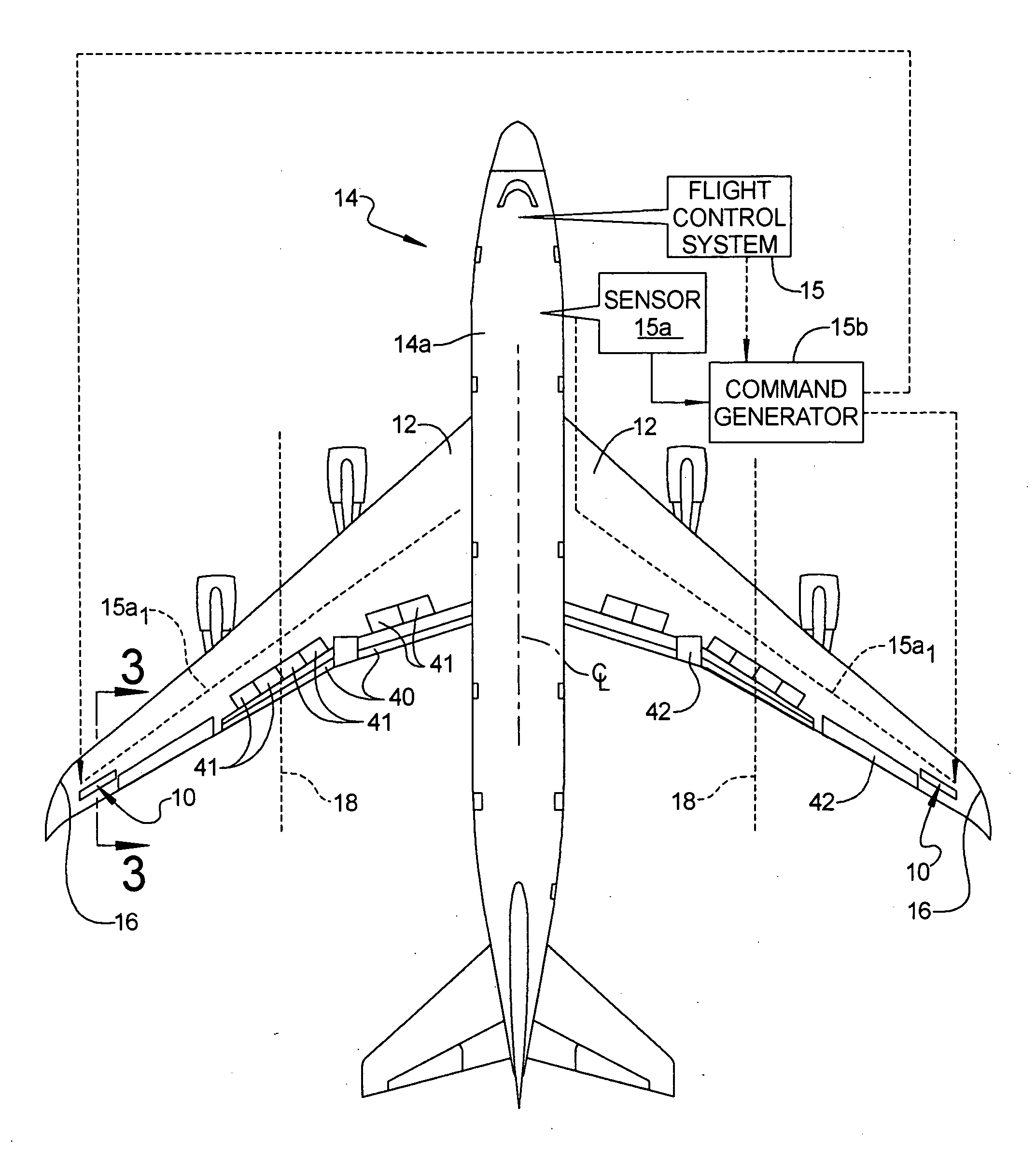
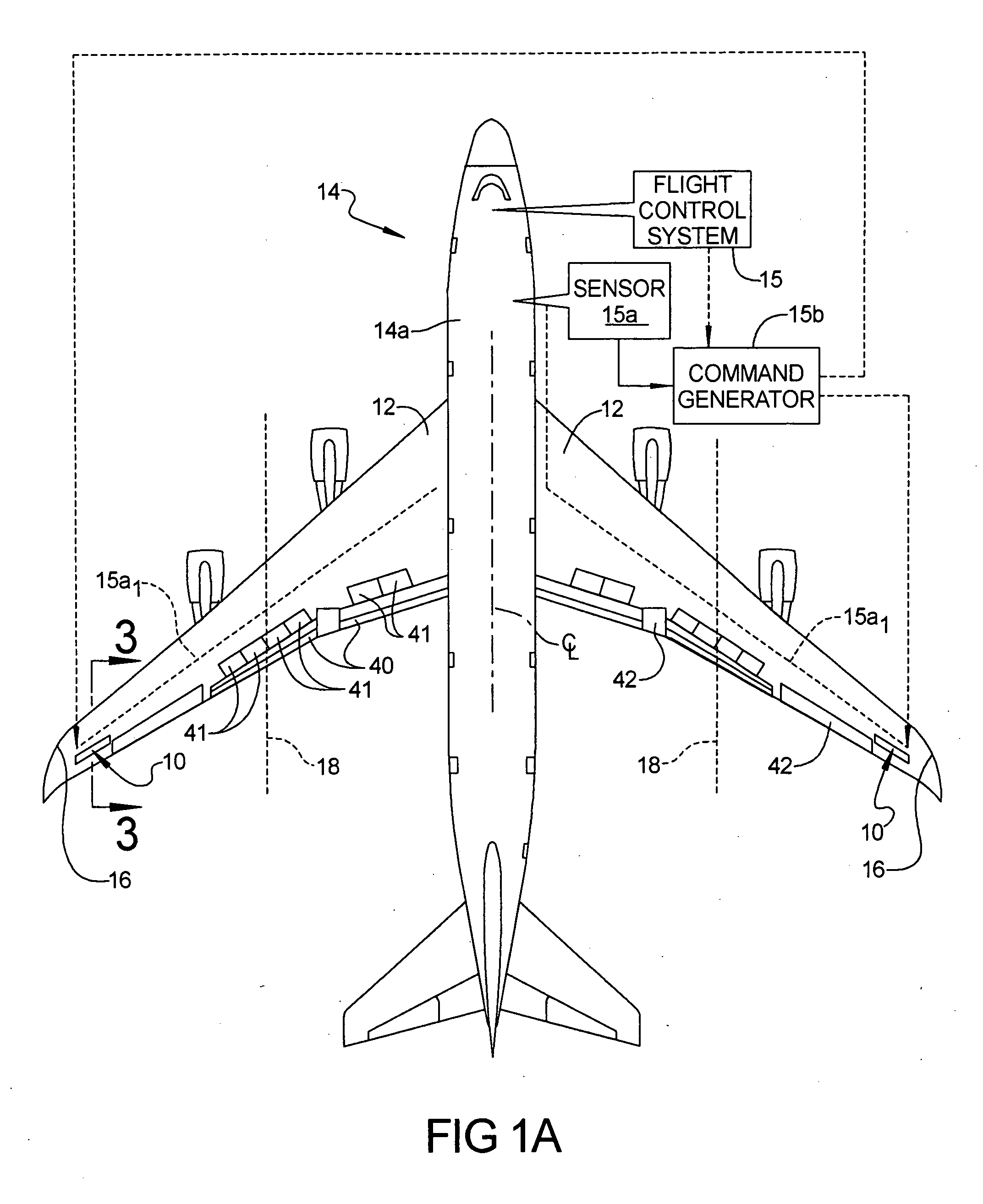
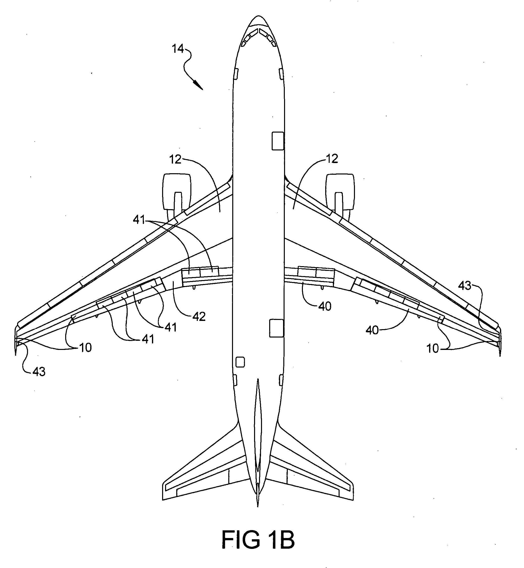
[0017] Referring to FIG. 1A, a wing load alleviation apparatus 10 in accordance with a preferred embodiment of the present invention is illustrated located in each wing 12 of an aircraft 14. In this example the aircraft is a modern day, commercial jet aircraft having a flight control system 15, although it will be appreciated that the apparatus 10 could be employed in propeller or turboprop driven aircraft as well. The aircraft may be a subsonic transport equipped with a swept, moderate or high aspect ratio wing and turbofan engines. The wing could employ metallic structure such as structure using aluminum alloy material, or composite structure such as structure using carbon-epoxy or other composite material, or a hybrid of metallic and composite structure. The apparatus 10 may be located at any outboard spanwise po...


PUM


Abstract

A wing load alleviation system and method for alleviating the lift-inducing structural-bending force (i.e., moment) experienced by each of the wings of an aircraft. The apparatus includes a deployable panel and an actuator mounted in each wing. The actuators are responsive to a command generator. The actuator is mounted inside the wing and the panel is mounted flush with an outer surface of its respective wing. Each panel can be moved between a retracted position, where it has no affect on airflow moving over the wing, to a deployed position in which it deflects air off of the wing. Each panel is preferably located at a span-wise location at least about halfway along the length of the wing toward the wing tip, and more preferably at least in part outboardly of the outboard-most trailing edge device in the wing. The apparatus effectively shifts the lift-inducing structural-bending forces experienced by the wing more inboard towards the fuselage.

Description

FIELD OF THE INVENTION [0001] The present invention relates to aircraft, and more particularly to a system adapted to alleviate lift-induced structural-bending loads experienced by the wings of an aircraft during flight. BACKGROUND OF THE INVENTION [0002] The wing structure of a typical, modern day jet aircraft is designed at least in part by considering critical loads at limiting flight or ground conditions. Typically, a limiting flight condition is one at which high load factors are experienced, and is one that is usually avoided during normal flight operations. The wing structure has to be designed with sufficient strength to thus be able to accommodate the high load factors that are experienced at a limiting flight condition, even though such a condition will rarely, or possibly never, be encountered during flight of the aircraft. [0003] Designing wing structure to accommodate the high load factors that are experienced at limiting flight conditions requires that the wing spars a...

Claims


Application Information

Patent Timeline
Patent Type & Authority Applications(United States)
IPC IPC(8): B64C39/06
CPCB64C9/323B64C13/16Y02T50/44Y02T50/40B64C9/00
Inventor DEES, PAUL W.SANKRITHI, MITHRA
Owner THE BOEING CO
Why Eureka
Try Eureka